


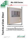

Mx-1000 Series
34 Moorland Way : Nelson Park : Cramlington
Northumberland : NE23 1WE
Tel: +44 (0)1670 707 111
Fax: +44 (0)1670 707 222
www.Advel.co.uk Email: Sales@Advel.co.uk
1 List Of Contents
1 List Of Contents.......................................................................................................................................2
2 List Of Figures.........................................................................................................................................3
3 List of Tables...........................................................................................................................................3
4 Introduction .............................................................................................................................................4
5 Overview of Installation and Commissioning .........................................................................................4
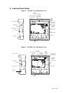
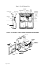
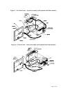
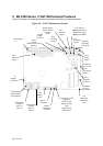
6 Internal Panel Views................................................................................................................................5
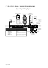
7 Mx-1016 16 -Zone – Typical Wiring Schematic.....................................................................................8
8 Circuit Connection Details ......................................................................................................................9
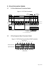
8.1 2-16 Zone Motherboard Termination Details..................................................................................9
8.2 16 Zone Expansion Board Termination Details...............................................................................9
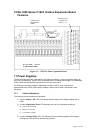
9 Mx-1000 Series C1627 Motherboard Features.....................................................................................10
10 Mx-1000 Series C1632 16-Zone Expansion Board Features.............................................................11
11 Power Supplies ..................................................................................................................................11
11.1 Visual indications ..........................................................................................................................11
11.2 Battery Disconnect.........................................................................................................................12
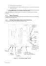
11.3 32-Zone Power Supply Features And Connections.......................................................................12
12 Installation.........................................................................................................................................13
12.1 Electrical Safety.............................................................................................................................13
12.1.1 IMPORTANT NOTES ON BATTERIES:............................................................................13
12.1.2 ELECTRICAL SAFETY:......................................................................................................14
12.2 Installation Instructions .................................................................................................................15
12.2.1 Mx-1000 Series Panel Installation Instructions .....................................................................15
12.2.2 Installation And Connection Of The C1631 Repeater Interface............................................17
13 Commissioning..................................................................................................................................19
13.1 Introduction ...................................................................................................................................19
13.2 Commissioning Checklist..............................................................................................................19
13.3 An Overview Of The Commissioning Procedure..........................................................................19
13.4 Pre-Commissioning Wiring Check................................................................................................20
13.5 Powering up...................................................................................................................................21
13.6 Configuration.................................................................................................................................21
13.6.1 Basic Default Configuration..................................................................................................21
13.6.2 Site-Specific Configuration. ..................................................................................................21
13.7 Commissioning Procedure.............................................................................................................21
13.7.1 Alarm Circuits .......................................................................................................................21
13.7.2 Commissioning zones............................................................................................................22
13.7.3 Commissioning the Class Change Input................................................................................23
13.7.4 Commissioning the Fire and Fault Routing Outputs..............................................................23
13.7.5 Commissioning the Fire Protection control signal.................................................................23
13.7.6 Commissioning ancillary inputs ............................................................................................24
13.7.7 Commissioning ancillary outputs ..........................................................................................24
13.7.8 Commissioning repeaters.......................................................................................................24
14 User Controls and Indications............................................................................................................25
14.1 User Indications [showing optional clock module] .......................................................................25
14.2 User Controls [showing optional clock module] ...........................................................................26
15 Operating the Engineer’s functions ...................................................................................................27
15.1 Engineer’s Zone/Output Configuration Process:...........................................................................27
15.2 Zone or Output Configuration .......................................................................................................27
15.3 To Restore the Factory Default Configuration for Zones & Outputs: ...........................................28
15.4 Engineer’s Zone/Output Configuration Time-out Warning:..........................................................29
15.5 Invalid Configuration conditions:..................................................................................................29
15.6 List of configuration DIL switches and their functions.................................................................29
15.7 Configurable Options via DIL switch selection on Repeater Interface Board:..............................32
15.8 Configuring the Fire Routing, Fire Protection and Fault routing O/Ps..........................................33
15.9 Enable/disable earth fault monitoring............................................................................................33
ISO9001
ISO9001