


○ Fire and fault routing signalling should be tested.
WARNING: Before testing, the engineer must be aware both of the operation of all
devices fitted to the auxiliary circuits and of the consequences of their operation.
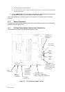
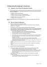
13.4 Pre-Commissioning Wiring Check
NOTE: This pre-commissioning wiring check procedure should be followed to test all
wiring prior to specific commissioning of any detection, alarm and auxiliary circuits.
1. Ensure that no devices are connected to the detection zones and alarm circuits, but that
the cables are linked through at the device locations to achieve a continuous circuit.
2. Ensure that the resistance of all cables to earth and between cores is at least 2MΩ.
Check the following:
i) Positive to earth resistance is 2MΩ or greater.
ii) Negative to earth resistance is 2MΩ or greater.
iii) Positive to negative resistance is 2MΩ or greater.
3. Connect a wire link as the end-of-line device on each of the zones and alarm circuits. At
the panel end, measure the resistance across the positive & negative ends of the cables
for each of the circuits; ensuring the value does not exceed 20Ω. Remember to remove
the wire links after the tests.
Correct polarity throughout all circuits must be maintained. Rectify any faults.
All bells, detector heads and call points should now be connected and the correct end-of-line
devices fitted. Use the spare end-of-line devices supplied and leave the EOL devices in the panel
terminals at this stage. Remember to remove any links fitted to detector bases. Be very careful to
maintain correct polarity at each device.
Warning: Intrinsically safe zone arrangement.
○ End-of-line capacitors cannot be connected to zones monitoring Intrinsically Safe
detection devices in hazardous areas. To do so will risk causing an explosion in the
hazardous area. End-of-line resistors with a value of 3K9Ω must be used, which
comply with the requirements laid down in the installation data sheets provided with the
I.S. barrier and the I.S. fire detection devices.
○ In order for detector head removal monitoring to function correctly when resistors are
used as the end-of-line devices, any diodes in the detector bases that are in circuit
when the detector head is removed must be disconnected.
○ The panel must be configured to monitor Intrinsically Safe zones.
○ The first device on an Intrinsically Safe zone must be an I.S. Zener Barrier or Galvanic
Isolator. Detectors and Manual Call Points on the Safe side of the barrier are not
permitted.
○ To comply with the requirements of BS5839, all manual call points should be located in
the zone cabling between the I.S. Barrier/Isolator and the first detector. Any manual call
point or detector located on the “end-of–line” side of a detector will be rendered
inoperative if the detector head is removed.
Page 20 of 40