


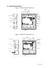
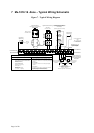
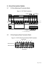
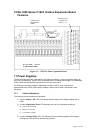
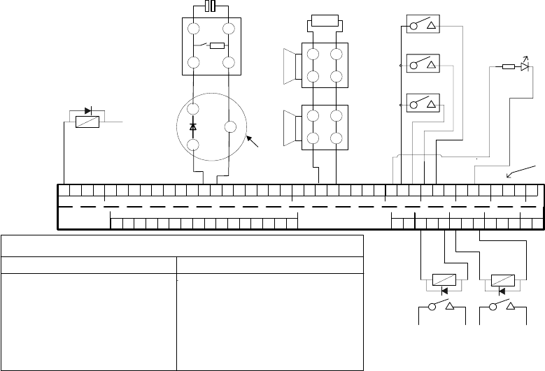
7 Mx-1016 16 -Zone – Typical Wiring Schematic
Figure 7 – Typical Wiring Diagram
Zone O/Ps
1234
Zone Circuits
Zone Circuits
Alarm Circuits
Aux DC
Inputs Outputs
AB
Lower terminal tier
Upper terminal tier
Lower terminal tier
Upper terminal tier
Fault Routing
Aux DC Fire Routing Fire Protection
N/C
RST
Scn
Repeater
BActEvacDisCl/CRSTEvacSil
0V
24V4 -4 +3 +2 +1 + 3 -2 -1 -8 -8 +7 -6 -5 -4 -3 -2 -1 -1 + 2 +3 +4 +5 +6 +7 +
RST
N/OPO/-PC/+O/-PC/+
C/-PO/+
0V
24V9 + 10 + 11 + 12 + 13 + 14 + 15 + 16 +16 -9 - 10 - 11 - 12 - 13 - 14 - 15 -
+
-
+
-
+
-
+
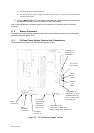
22uF capacitor end-of-line device
-observe polarity
Manual call point
with 680R resistor
Detector base with
Schottky Diode
1 2
1A 2A
Typical Zone Wiring
3K9 resistor
end-of-line device
-
-
+
+
-
-
+
+
Typical Alarm Circuit Wiring
Typical Input Circuit Wiring
for Remote Silence, Evac, Reset &
Class Change,
2k2 0.5W
resistor
Typical remote
output wiring
Repeater Wiring - see
Figure 9 - Repeater
connection diagram
Connect
to Aux DC
24 V
24 V DC
relay
Typical zonal
output wiring
Field relay spec:
Coil resistance - 2.6 to 4.5 k Ohms
Voltage 24 V DC Nom
[min 18 V, max 30 V]
Fitted with suppression diode as shown.
Relay local to fire
routing equipment
equipment
Relay local to fault
routing equipment
equipment
Fire and Fault Routing
output wiring shown for
the monitored/powered
configuration
For Fire Routing and Fire Protection O/Ps:
Quiescent: 5 V DC
Active [fire]: 24 V nom]
For Fault Routing O/P:
Quiescent: 24 V DC [nom]
Active [fault]: 5 V
Connections:
Observe correct polarity.
[+ = Positive, - = Negative]
Fire Routing, Fault Routing & Fire Protection O/P configuration - Output specification:
When configured as monitored/powered outputs:
For Fire Routing and Fire Protection O/Ps:
Volt free relay contacts shown in quiescent [de-energised]
condition.
For Fault O/P:
Volt free relay contacts shown in healthy [energised]
condition.
Connections:
Connect to normally open or normally closed contact as
required.[P= Pole, C= Closed, O = Open]
Applied voltage must not exceed 30 V DC.
When configured as volt-free changeover relays :
-ve
Terminal identification
notes:
Cl/C = Class Change.
B Act = Buzzer Active
RST = Reset
[Normally open switch contacts]
Page 8 of 40