


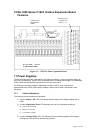

12.2 Installation Instructions
1. Carefully remove the control panel from the packing and lie the panel on a flat surface.
2. Open the door of the panel.
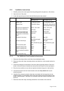
3. Locate the spares bag and check that the following items are present:
Type
Quantity Description
Mx-1002 / 04 Mx-1008 /16 / 32
1 Mains Fuse T1AH250V 20mm T3.15AH250V 20mm
1 Battery Fuse F2AL250V 20mm F5AL250V 20mm [8/16]
F6.3AL250V 20mm [32]
* End-Of-Line capacitors for
normal zone monitoring
22 µF, 35 V axial.
*[2/4 off]
22 µF, 35 V axial.
*[8/16/32 off]
* End-Of-Line resistors for
alarm circuits and zones
configured as Intrinsically
Safe.
3k9 0.25W
*[4/8 off]
3k9 0.25W
*[12/20/36 off]
1 Engineer’s door keys Key Ref.:
801 [Flat key type]
Key Ref.:
801 [Flat key type]
1 Access Control keys Key Ref.:
801 [Tubular key type]
Key Ref.:
801 [Tubular key type]
1 Positive battery lead Red Red
1 Negative battery lead Black Black
1 Battery coupling lead Blue Blue
4 Battery terminal insulation
boot
[32 zone panel only]
N/A Mx-1032 only
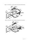
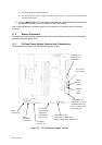
12.2.1 Mx-1000 Series Panel Installation Instructions
1. Disconnect the display ribbon cable from the motherboard header.
2. Disconnect the earth strap connecting the door and back-box via the spade terminal on
the door.
3. Unscrew the hinge pin at the bottom of the door whilst supporting the door. Swing the
bottom of the door clear of the back-box and pull the door away from the top hinge pin.
4. Place the door carefully to one side and replace the bottom hinge pin in the back-box.
5. Unscrew and remove the two lower chassis screws and only slacken the top two
mounting screws.
6. Carefully lift the chassis upward to align the screw heads with the large holes in the
chassis keyholes. Lift the chassis clear of the upper screws and rest the chassis in the
bottom of the enclosure. Take care not to strain the wires that remain connected to the
back-box.
7. Disconnect the earth strap connecting the backbox and chassis at the earth bar.
Page 15 of 40