a) Switching regulator is malfunctioning
b) The power supply output voltage has been incorrectly set to a value less than the terminal
voltage of the batteries
4) A yellow ‘Mains Fault’ LED. This denotes that the mains voltage has failed or is less than
the required minimum for correct operation of the power supply.
Note: Fault indications do not become active for a minimum of 10 seconds after the fault has
occurred.
11.2 Battery Disconnect
The supply provides a battery disconnect facility which disconnects the batteries when the battery
terminal voltage falls below 19.5V.
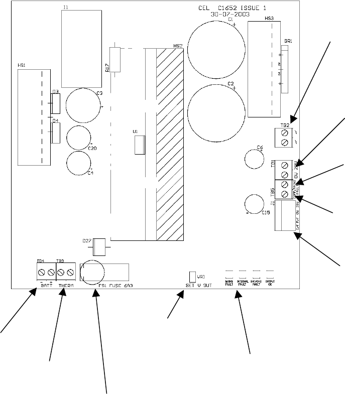
11.3 32-Zone Power Supply Features And Connections
Figure 12 shows the layout of the 32 zone panel power supply.
FS1 Battery
fuse [6.3 A]
Battery
connections
Battery
Thermistor
connections
DC supply
output voltage
adjustment
potentiometer
[factory set].
LED indicators for:
Mains fault, Internal Fault,
Battery/Charge Fault, Output O.K.
4-way header for
connector to 32 zone
motherboard for DC
power, common fault
and mains fault
Common
Fault
Output
Mains
Fault
Output
28V, 0V DC
Power output
Secondary AC
Supply from
transformer
Figure 12 – 32-Zone Power Supply Layout
Page 12 of 40


