


Internet Version for Reference Only
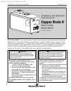
Bradford White
Page 6
Copper Brute II
Page 7
the outdoors through horizontal ducts, each opening
shall have a minimum free area of not less than
1 square inch per 2000 Btu/hr (11 square cm/kW) of
total input rating of all equipment in the enclosure.
Table 3 shows data for this sizing method, for each
Copper Brute II model.
Method 2: One permanent opening, commencing
within 12 inches (30 cm) of the top of the enclosure,
shall be permitted. The opening shall directly
communicate with the outdoors or shall communicate
through a vertical or horizontal duct to the outdoors
or spaces that directly communicate with the outdoors
and shall have a minimum free area of 1 square inch
per 3000 Btu/hr (7 square cm/kW) of the total input
rating of all equipment located in the enclosure. This
opening must not be less than the sum of the areas of
all vent connectors in the conned space.
Other methods of introducing combustion and
ventilation air are acceptable, providing they conform
to the requirements in the applicable codes listed
above.
In Canada, consult local building and safety
codes or, in absence of such requirements, follow CSA
B149.1.
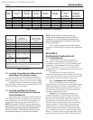
Each Opening*
Model Square inches Square cm
500 125 807
750 188 1213
1000 250 1613
1250 313 2020
1500 375 2420
1750 438 2826
2000 500 3226
*Net Free Area in Square Inches / Square cm
Area indicated is for one of two openings; one at oor level and
one at the ceiling, so the total net free area could be double the
gures indicated.
This chart is for use when communicating directly with the
outdoors. For special conditions and alternate methods, refer to
the latest edition of ANSI Z223.1.
Note: Check with louver manufacturers for net free area of
louvers. Correct for screen resistance to the net free area
if a screen is installed. Check all local codes applicable to
combustion air.
Table 3. Combustion Air Openings.
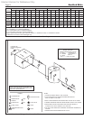
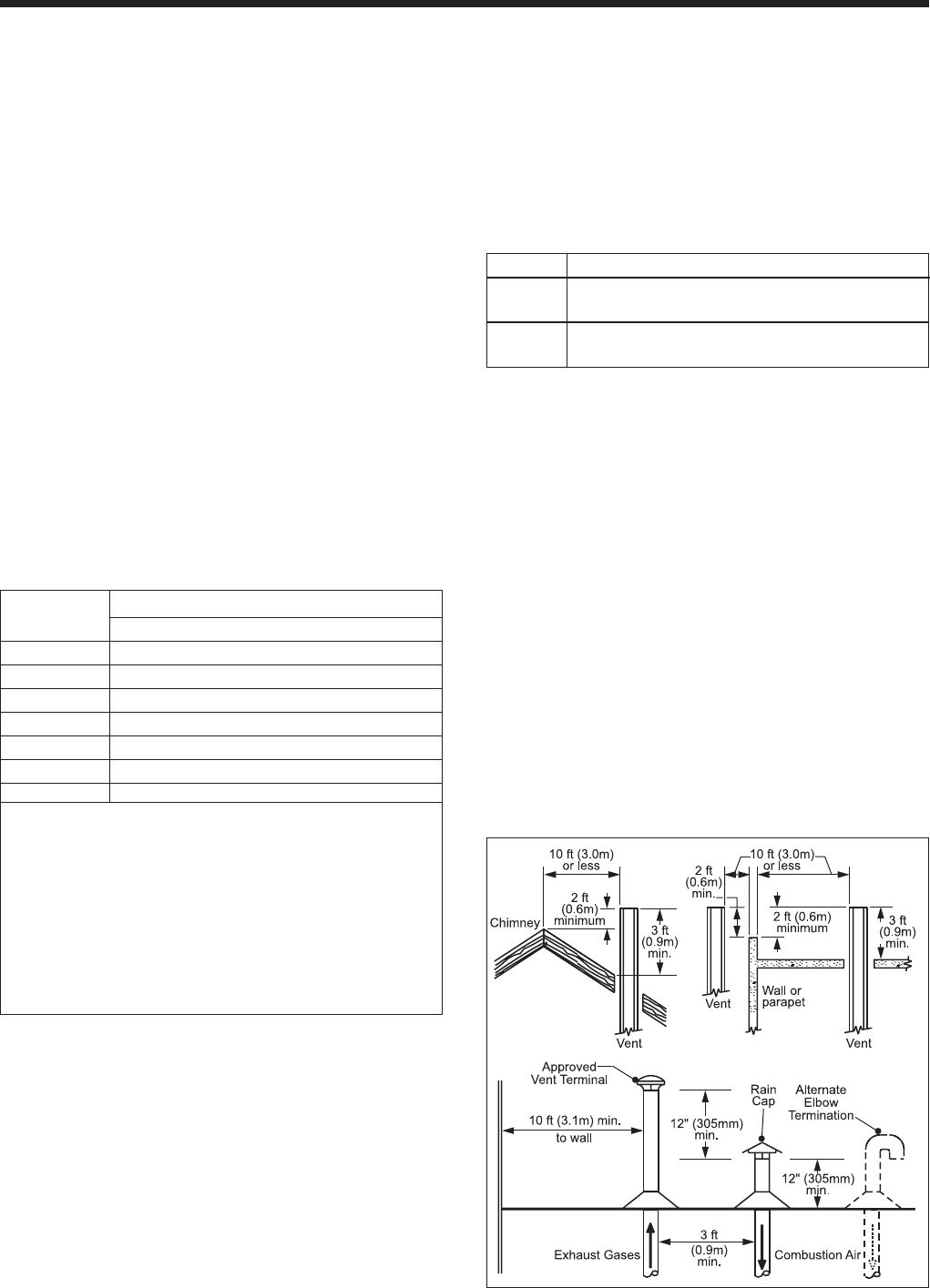
2.1.2 Intake Combustion Air
The combustion air can be taken through the
wall, or through the roof. When taken from the wall,
it must be taken from out-of-doors by means of the
Bradford White horizontal wall terminal (see Table 1).
When taken from the roof, a eld-supplied rain cap or
an elbow arrangement must be used to prevent entry of
rain water (see Figure 2).
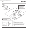
Use single-wall galvanized pipe, per Table
4, for the combustion air intake (see Table 1 for
appropriate size). Route the intake to the heater as
directly as possible. Seal all joints with tape. Provide
adequate hangers. The unit must not support the
weight of the combustion air intake pipe. Maximum
linear pipe length allowed is 50 feet (15.2m). Three
elbows have been calculated into the 50-foot (15.2m)
linear run. Subtract 10 allowable linear feet (3.0m) for
every additional elbow used (see Table 1). When fewer
than 3 elbows are used, the maximum linear pipe
length allowed is still 50 feet (15.2m).
Term Description
Pipe
Single-wall galvanized steel pipe, 24 gauge
minimum (either insulated or non-insulated)
Joint
Permanent duct tape or aluminum tape
Sealing
Table 4. Required Combustion Air Piping Material.
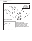
The connection for the intake air pipe is on
the lter box. The heaters may have venting and
combustion air ducting attached to the top or the back.
They are shipped with the connections at the top. For
attaching either or both pipes to the back, the mounting
anges are reversible by removing the mounting
screws and orienting the anges in the desired
position. Replace the screws after positioning anges.
Run a bead of silicone around the collar and slide the
pipe over the collar. Secure with sheet metal screws.
In addition to air needed for combustion, air
shall also be supplied for ventilation, including all air
required for comfort and proper working conditions
for personnel. The Copper Brute II loses less than 1
percent of its input rating to the room, but other heat
sources may be present.
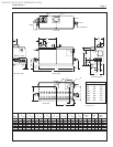
Figure 2. Combustion Air and Vent Through Roof.