


Internet Version for Reference Only
Bradford White
Page 22
Copper Brute II
Page 23
PUMP DLY (Pump Delay): On pump mounted
units, the heater mounted pump continues to run for
the time selected after the heat demand in the system is
satised. This setting also affects the 24VAC output on
the “PMP” “PMP” terminals (see section 5.2). These
terminals can power a contactor for a larger system
pump. Bradford White recommends a minimum pump
delay setting of 5 minutes. See section 6.3.6 for more
information. Note: In modes other than mode 6, the
pump will run continuously if the “HtD” and “ComD”
terminals are jumpered and not connected to a zone
valve or pump end switch, or other “contact closure”
device to indicate when the heat demand in the system
is satised. The pump will never run, and the heater
will never re, if the jumper is removed and the
terminals left empty.
OUTDOOR RESET (Modes 4 and 5) Outdoor
reset adjusts the target temperature based on the
outdoor air temperature and reset ratio. The reset ratio
is determined from the Boiler Start, Boiler Design,
Outdoor Start and Outdoor Design settings.
HEAT DEMAND – For heat demand to exist,
there must be continuity between the Com D (common
demand) and Ht D (heat demand) terminals. The heater
ships with a jumper between these terminals.
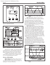
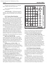
The control also evaluates the sensor(s) installed
in the system. If the control is not in warm weather
shutdown (WWSD), and the sensor(s) are below the
target temperature, the “Dem” segment is turned on
in the display. The control energizes the pump (on
pump mounted heater) and energizes the “PMP-PMP”
terminals. The pump symbol appears in the display
(see Figures 10 and 11). The control then operates the
stages to maintain the set point temperature.
Boiler Start (BOIL START) The BOIL
START temperature is the theoretical heater supply
temperature that the heating system requires when the
outdoor air temperature equals the OUTDR START
temperature setting.
EXAMPLE 1
DHW (Mode 3) Programming. For domestic
hot water systems up to 175°F / 79°C, use Mode 3 as
described below.
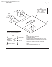
Step 1: Install the additional sensor into the
storage tank, wiring it to “SC2” and “SUPS” terminals
on the eld wiring panel (Figure 24).
Step 2: Press the three programming buttons to
enter “ADJUST” mode (Figure 10). Press “Item” to
select the programming item, and the arrow keys to
adjust the setting. “TARGET TANK” is desired tank
temperature. Recommended settings with a desired
tank temperature of 125°F:
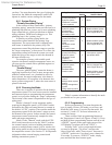
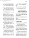
Example DHW Programming
Item F° C°
MODE 3 3
BOIL TARGET 140°F 60°C
TARGET TANK 125°F 52°C
DIFF TANK 2°F 1°C
BOIL MASS 1 1
DIFF 2°F 1°C
DLY 5:00 5:00
F° F° °C
Step 4: See section 6.3.11 Limit Controls. Set
both high limits 25°F / 14°C higher than “BOIL
TARGET” to allow for temperature rise across heat
exchanger. Manual high limits on water heaters have
a maximum 200°F / 93°C setting. (If water must be
at 175°F / 79°C or higher with a volume water heater
model, use Mode 1. For volume water applications
exceeding 200°F / 93°C, contact the factory.)
Fine tuning: For faster staging, increase “BOIL
TARGET” setting. Larger “DIFF TANK” and “DIFF”
settings will slow response to demand, but may save
energy.
If unit short cycles, enter Advanced Programming
mode (Section 6.3) and increase “BOILER MAX”
setting to the “BOIL TARGET” setting or higher. Set
“BOILER MIN” to 120°F / 49°C, and “STGMODE”
to PID. See section 6.3.12 Advanced Programming
Mode to enter Advanced Programming mode, or
contact the factory for assistance.
EXAMPLE 2
Hydronic Primary/Secondary (Mode 2)
Programming. MODE 2 is used in primary-secondary
piping hydronic systems without outdoor reset. Mode
5 adds outdoor reset.
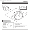
Step 1: Install the additional sensor in the
primary loop. This sensor should be installed as per
Section 6.2.4 under Primary Secondary Piping in this
manual, and wired to the “SC2” and “SUPS” terminals
on the eld wiring panel (Figure 24).
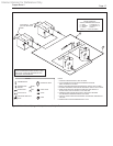
Step 2: Remove the factory-installed jumper
between the “HtD” and “ComD” terminals on the
eld wiring panel (Figure 24), and connect a zone
valve or pump end switch or other contact closure
device (aquastat, etc.) to these terminals to provide an
indication of heat demand in the system.
Note: The heater must have an indication of heat
demand to re. If a zone valve or pump end switch
is not connected to the “HtD” and “ComD” terminals,
the jumper must be left in place. However, the heater
pump (if equipped) and any pump connected to a
contactor wired to the PMP-PMP terminals on the
eld wiring panel will run continuously and not cycle
off according to the setting for the Pump Delay. In
addition, the LCD screen will always show “dem”
(demand) and will not allow cycling of the display to
verify all the sensor settings.