


Internet Version for Reference Only
Bradford White
Page 28
Copper Brute II
Page 29
signal to these terminals. The control energizes the
heater pump (if equipped), energizes the Pmp-Pmp
terminals, and turns on the heater pump segment in the
display. The control also turns on stage 1 of the heater.
Section 5.3 contains important information about
external staging controls and building automation
systems. Other wiring methods may be unsafe. The
wiring in Section 5.3 of this manual must be used.
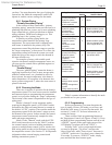
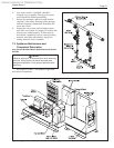
6.3.11 Limit Controls
In addition to the temperature control, Copper
Brute II appliances are tted with a manual reset
high limit and an automatic reset high limit. These
are located near the rear of the cabinet on the right
side, behind the slide out drawer (see Figure 17).
Both controls should be set at least 25°F higher than
the target temperature to avoid short cycling. To set
these controls, remove the control panel cover and
pull the control panel out to gain access. Appliances
with reversed heat exchangers have the limit controls
relocated to the left side of the appliance. The left
access door must be removed to gain access to the
limit controls on these appliances.
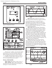
6.3.12 Advanced Programming Mode
Advanced programming mode allows the
installer to set the temperature control for proportional
staging. In advanced programming mode, the
interstage differential, interstage delay, interstage on
and off delay, and minimum time on and off are all set
manually.
NOTE: Advanced programming mode is rarely
required. It is intended for advanced installers,
and only when the application demands such
programming.
To enter advanced programming mode, remove
the bezel on the temperature control by pulling out at
the bottom. Remove the small Phillips head screw to
access the dip switch. The dip switch is mounted on a
circuit board.
Locate the letter “A” on the circuit board and
slide the corresponding dip switch toward the letter
“A”. The default setting of this dip switch is toward
the “OFF” lettering on the circuit board.
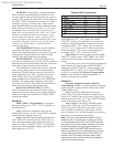
6.4 Operating the Burner and Set Up
6.4.1 Set Up for 0 to 2500 Feet Altitude
The Copper Brute II appliance utilizes a modular
design to achieve its stage-ring. The setup must be
checked before the unit is put in operation. Problems
such as failure to start, rough ignition, strong exhaust
odors, etc. can be due to improper setup. Damage to
the Copper Brute II resulting from improper setup is
not covered by the limited warranty.
1. Using this manual, make sure the installation
is complete and fully in compliance with the
instructions.
2. Determine that the appliance and system are
lled with water and all air has been bled from
both. Open all valves.
3. Observe all warnings on the Operating
Instructions label and turn on gas and electrical
power to appliance.
4. Switch on the heater power switch located on the
right side of the unit.
5. The heater will enter the start sequence, as long
as the unit is being called for heat. The blower
and pump come on for pre-purge, then the ignitor
warm-up sequence starts and after the ignitor
warm-up is complete and all safety devices are
veried, the gas valves open. If ignition doesn’t
occur, check that there is proper gas supply.
Wait 5 minutes and start the unit again. During
initial start up, air in the gas line may cause the
heater to "lock out" during the rst few trials
for ignition. Depending on the ignition modules
installed, the manual reset button on the ignition
modules may need to be depressed to restart the
heater.
6. When the unit is running, the supply gas pressure
must be checked. Inlet gas pressure must not
exceed 13" W.C. (3.2kPa). The minimum inlet
gas pressure is 5" W.C. (1.2kPa).
7. Once the inlet gas pressure is veried, the
outlet gas pressure from each valve (manifold
gas pressure) must be checked, and adjusted, if
necessary. The manifold gas pressure must be
2.5" W.C. (0.62kPa).
8. Complete the setup by checking the CO
2
at the
outlet of the unit. The CO
2
should be 8% for
natural gas, or 9.2% for propane.
9. After placing the heater in operation, the
Burner Safety Shutoff Device must be tested.
To test:
(a) Close gas shutoff valve with burner
operating.
(b) The ame will go out and blower will
continue to run for the post purge cycle.
One additional attempt to light will follow.
Ignition will not occur as the gas is off. The
ignition control will lockout, and will have
to be reset before the unit will operate.
(c) Open gas shutoff valve. Restart the
appliance. The ignition sequence will
start again and the burner will start. The
appliance will return to its previous mode
of operation.
NOTE: Models 1000 - 2000 have two ignition controls
and two ignitors, which work independently of one
another. If the ignition control for stages 1 and 2 fails
to properly light the main burners for those stages, the
second ignition control will still be active, and will be
able to energize stages 3 and 4. This, of course, will
only occur if all other safety devices conrm that the
unit will run in a safe condition.