


Internet Version for Reference Only
Bradford White
Page 24
Copper Brute II
Page 25
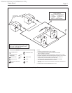
If the heater is not a pump mounted model, a
24VAC pump contactor may be connected to the
“PMP” terminals to control a eld installed pump.
Program the temperature control to use “Mode
2.” The AUTO/MAN switch must be in the AUTO
position in this mode.
Mode 4: Hydronic outdoor reset system
without primary / secondary piping.
Bradford White strongly suggests the use of
primary secondary piping with the Copper Brute II
heater. This piping style best ensures that the Copper
Brute II will have proper water ow. However, non-
primary secondary methods can be used successfully,
so this section has been included.
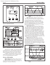
Install the outdoor reset sensor, Bradford White
part number R2014000, and connect the leads to the
“OD S” and “S C2” terminals.
You must provide an indication of the system’s
heat demand by removing the jumper across the
“ComD” and “HtD” terminals on the eld wiring
panel and connecting a zone valve or zone pump end
switch, thermostat, aquastat or other contact closure to
these terminals. If the “ComD” and “HtD” terminals
are left jumpered, the control will always see a heat
demand and remain in “Dem” mode, with the boiler
pump running continuously. See Section 5.2 for more
information.
Reset Override: An additional thermostat or aquastat
may be connected to the “Set D” and “Com D”
terminals. A call for heat from either of these controls
will start the heater’s pump and cause the heater to re.
If the heater is not a pump mounted model, a
24VAC pump contactor may be connected to the
“PMP” terminals to control a eld installed pump.
Program the temperature control to use “Mode
4.” The AUTO/MAN switch must be in the AUTO
position in this mode.
Mode 5: Primary secondary piping with
outdoor reset.
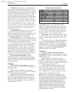
Install the outdoor reset sensor, Bradford White
part number R2014000, and connect the leads to
the “OD S” and “S C2” terminals. Install a “supply
sensor” in the primary loop using the Bradford White
part number R2014800 sensor (included with every
heater). Connect the sensor to the “S C2” and “SUP S”
terminals.
You must provide an indication of the system’s
heat demand by removing the jumper across the
“ComD” and “HtD” terminals on the eld wiring
panel and connecting a zone valve or zone pump end
switch, thermostat, aquastat or other contact closure to
these terminals. If the “ComD” and “HtD” terminals
are left jumpered, the control will always see a heat
demand and remain in “Dem” mode, with the heater
pump running continuously. See Section 5.2 for more
information.
A secondary aquastat, such as for a separate heat
exchanger for DHW, can be connected to the “Set D”
and “Com D” terminals. A call for heat from these
controls will start the heater pump and cause the heater
to re.
If the heater is not a pump mounted model, a
24VAC pump contactor may be connected to the
“PMP” terminals to control a eld installed pump.
Program the temperature control to use “Mode
5.” The AUTO/MAN switch must be in the AUTO
position in this mode.
Mode 6: Heater with external staging
control (multiple boiler control,
building automation system, energy
management system, etc.)
Leave the jumper installed between “Ht D” and
“Com D” terminals. There are terminals on the eld
wiring panel that must be wired per the instructions
in section 5.3 of this manual. Other wiring methods
may be unsafe. The wiring in section 5.3 of this
manual must be used.
The AUTO/MAN switch is located on the circuit
board in the slide-out control panel on the front of the
heater. This switch is placed in the manual position
(MAN) when an external control is controlling the
heater stages.
Program the temperature control to use Mode 6.
Mode 6 tells the heater control that an external staging
control is being used.
6.3 Advanced Topics
For most installations, section 6.2 provides all
the information required to set up the Copper Brute II
heater, and this section should be skipped. Continue
setup in section 6.4.
This section provides denitions of the
programming parameters, advanced programming
topics, and other information that may be of interest.
Advanced programming mode allows the
installer to set the temperature control for proportional
staging. In advanced programming mode, the
interstage differential, interstage delay, interstage on
and off delay, and minimum time on and off are all set
manually.
NOTE: Advanced programming mode is not required
in most applications, and is intended for advanced
installers only.
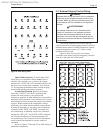
To enter advanced programming mode, remove
the bezel on the temperature control by pulling out at
the bottom. Remove the small Phillips head screw to
access the dip switch. The dip switch is mounted on
a circuit board. Locate the letter “A” on the circuit
board and slide the corresponding dip switch toward
the letter “A”. The default setting of this dip switch is
toward the “OFF” lettering on the circuit board.