


Internet Version for Reference Only
Bradford White
Page 18
Copper Brute II
Page 19
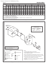
4.4 Combined Water Heating (potable)
and Space Heating — Water Heater
NOTE: These systems are not allowed in all localities.
Be sure to consult local codes.
Piping and components connected to this water
heater for the space heating application shall be
suitable for use with potable water.
Toxic chemicals, such as used for heater
treatment, shall not be introduced into the potable
water used for space heating.
This water heater when used to supply potable
water shall not be connected to any heating system
or component(s) previously used with a non-potable
water heating appliance.
When the system requires water for heating at
temperatures higher than required for other uses,
an anti-scald mixing or tempering valve shall be
installed to temper the water for those uses in order
to reduce scald hazard potential.
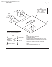
4.5 Freeze Protection – Water Heater
Although Copper Brute II water heaters are
design-certied for outdoor installations, such
installations are not recommended in areas subject to
freezing temperatures, unless proper precautions are
taken.
Power outage, interruption of gas supply, failure
of system components, activation of safety devices,
etc., may prevent a heater from ring. Any time a
heater is subjected to freezing conditions, and the
heater is not able to re, and/or the water is not
able to circulate, there is a risk of freezing in the
heater or in the pipes in the system. When water
freezes, it expands. This can result in bursting of pipes
in the system, or damage to the heater, which could
result in leaking or ooding conditions.
Contact the local factory representative or
Bradford White for additional information.
SECTION 5.
Electrical Connections
WARNING
The appliance must be electrically grounded in
accordance with the requirements of the authority
having jurisdiction or, in the absence of such
requirements, with the latest edition of the National
Electrical Code, ANSI/NFPA 70, in the U.S. and
with latest edition of CSA C22.1 Canadian Electrical
Code, Part 1, in Canada. Do not rely on the gas
or water piping to ground the metal parts of the
heater. Plastic pipe or dielectric unions may isolate
the heater electrically. Service and maintenance
personnel, who work on or around the heater, may
be standing on wet oors and could be electrocuted
by an ungrounded heater.
Single pole switches, including those of safety
controls and protective devices must not be wired in a
grounded line.
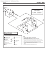
All electrical connections are made in the eld
wiring terminal strip, which is located at the right side
of the appliance.
NOTE: All internal electrical components have been
prewired. No attempt should be made to connect
electrical wires to any other location except the wiring
box.
5.1 Main Power
Connect a 15 amp. fused, 120-volt supply to the
main power switch (hot leg is connected directly to
switch). Neutral leg is connected directly to the white
wire. Ground wire can be connected to the grounding
screw in the box or on the switch.
Wiring diagrams are shown in Section 10 in
Figures 18 through 22. Field wiring is shown in
Section 10 in Figures 23 and 25.
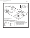
5.2 Temperature Control
5.2.1 Temperature Control Description
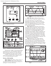
The eld wiring panel is located on the right side
of the heater, and is shown in Figure 8. The following
components are connected to the eld wiring panel:
Temperature sensor: The sensor supplied loose
with the heater is installed in the piping or tank, per
the suggested piping diagrams, and connected to the
“S C2” and “SUP S” terminals. See section 6.2 for
“Mode” denitions and Figures 24 and 25 for eld
wiring schematics.
Field Installed Pump: A pump contactor can
be wired to the “PMP” and “PMP” terminals (these
terminals supply 24VAC to close the contactor
whenever the heater pump would be operated). Note
that in some cases, the heater pump is operated
continuously.
External Alarm: An external power supply and
alarm can be connected to the “ALRM” and “ALRM”
terminals. In the event of an ignition system lockout, a
contact closure occurs across these terminals.
External Heat Demand Indication: 24VAC
is present across the “HT OUT” and “LWCO GND”
terminals whenever the temperature control sees a
system heat demand. This can be used to power a
contactor (0.5 Amp, maximum) for devices operated
whenever the heater could re (combustion air fans,
motorized louvers, etc.) NOTE: In some cases, the
temperature control will always see a heat demand
in the system, such as when the “Ht D” and Com D”
terminals are jumpered.