


Internet Version for Reference Only
Bradford White
Page 12
Copper Brute II
Page 13
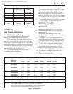
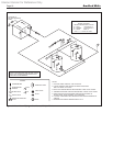
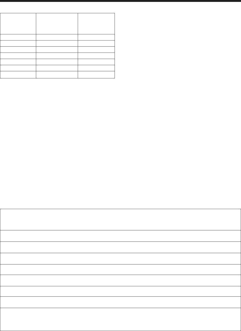
Outdoor Vent Outdoor
Model (Size) Terminal Combustion
Air Terminal
500 20254701 D2007900
750 20254703 D2007900
1000 20254705 D2008000
1250 D2007700 D2008000
1500 D2007700 D2008000
1750 D2007800 D2008000
2000 D2007800 D2008200
Table 6. Vent Terminals for Outdoor Units.
SECTION 3.
Gas Supply and Piping
3.1 Gas Supply and Piping
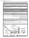
Gas piping should be supported by suitable
hangers or oor stands, not by the appliance.
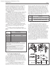
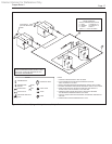
The Copper Brute II gas train allows the user to
pipe the gas from either the right side or the left side
of the unit. As shipped, the right side of the gas train is
capped off, and there is a manual valve on the left side.
If desired, the manual valve on the left side of the gas
train may be moved to the right side, and the cap on
the right side may be moved to the left.
Review the following instructions before
proceeding with the installation.
1. Verify that the appliance is tted for the proper
type of gas by checking the rating plate. Copper
Brute II heaters are equipped to operate at
elevations up to 10000 feet (3050m). Copper
Brute II heaters may be adjusted to operate
properly at altitudes above 2500 feet (see Section
6.4.2) and the input will be reduced if the heating
value of the gas supply is below sea level values.
2. The maximum inlet gas pressure must not exceed
13" W.C (3.2kPa). The minimum inlet gas
pressure is 5" W.C. (1.2kPa).
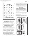
3. Refer to Table 7, size supply.
4. Run gas supply line in accordance with all
applicable codes.
5. Locate and install manual shutoff valves in
accordance with state and local requirements.
6. A sediment trap must be provided upstream of
the gas controls.
7. All threaded joints should be coated with
piping compound resistant to action of liqueed
petroleum gas.
8. The appliance and its individual shutoff valve
must be disconnected from the gas supply piping
during any pressure testing of that system at test
pressures in excess of 1/2 PSIG (3.45kpa).
9. The unit must be isolated from the gas supply
system by closing its individual manual shutoff
valve during any pressure testing of the gas
supply piping system at test pressures equal to or
less than 1/2 PSIG (3.45kpa).
10. The appliance and its gas connection must be
leak tested before placing it in operation.
11. Purge all air from gas lines.
Distance from Gas Meter
or Last Stage Regulator
Model and
Gas Type 0-100' 0-31m 100-200' 31-61m 200-300' 61-91m
500 natural 1-1/2" 3.8cm 2" 5.1cm 2" 5.1cm
500 propane 1" 2.5cm 1-1/2" 3.8cm 1-1/2" 3.8cm
750 natural 2" 5.1cm 2" 5.1cm 2-1/2" 6.4cm
750 propane 1-1/2" 3.8cm 1-1/2" 3.8cm 2" 5.1cm
1000 natural 2" 5.1cm 2-1/2" 6.4cm 3" 7.6cm
1000 propane 1-1/2" 3.8cm 2" 5.1cm 2-1/2" 6.4cm
1250 natural 2-1/2" 6.4cm 2-1/2" 6.4cm 3" 7.6cm
1250 propane 2" 5.1cm 2" 5.1cm 2-1/2" 6.4cm
1500 natural 2-1/2" 6.4cm 3" 7.6cm 3" 7.6cm
1500 propane 2" 5.1cm 2-1/2" 6.4cm 2-1/2" 6.4cm
1750 natural 2-1/2" 6.4cm 3" 7.6cm 3" 7.6cm
1750 propane 2" 5.1cm 2-1/2" 6.4cm 2-1/2" 6.4cm
2000 natural 3" 7.6cm 3" 7.6cm 3-1/2" 8.9cm
2000 propane 2-1/2" 6.4cm 2-1/2" 6.4cm 3" 7.6cm
Notes:
1.These gures are based on 1/2" (0.12kPa) water column pressure drop.
2.Check supply pressure and local code requirements before proceeding with work.
3.Pipe ttings must be considered when determining gas pipe sizing.
Table 7. Gas Piping Size.