


Internet Version for Reference Only
Bradford White
Page 30
Copper Brute II
Page 31
6.4.2 High Altitude Adjustment and Set
Up
Copper Brute II appliances may be operated at
high altitude (7700 ft., 2347 m) with a reduction in
output of approximately 10%. At altitudes of less than
or more than 7700 ft. (2347 m) the appliance will
perform equally as well, but with differing reductions
in output. At elevations higher than 7700 ft. (2347
m) the reduction in output will exceed 10% and at
elevations below 7700 ft. (2347 m) it will be less than
10%. High altitude adjustment must not be made on
appliances operating at elevations below 2500 ft. (762
m).
No orice changes are required to adjust the
Copper Brute II appliances for high altitude. High
altitude adjustment is accomplished by adjustment of
the gas valve manifold pressure and the air shutter(s).
The required instruments used to assist in these
adjustments are a CO
2
or O
2
Analyzer and a U-Tube
Manometer or other device capable of reading a
pressure of 2.5-3.0 inches W.C. (0.62-0.75 kPa).
Start the adjustment process by checking the
CO2 in the “as installed” condition. Adjust the air
shutter(s) so that the CO
2
is about 8% or the O
2
is
about 6.8% for appliances operating on Natural Gas.
For appliances operating on LP Gas adjust the air
shutter(s) so that the CO
2
is about 9.2% or the O
2
is
about 6.8%. Appliances with two blowers should be
adjusted so that the air shutters below each blower are
open the same amount.
Once the CO
2
or O
2
has been set, the manifold
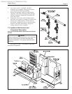
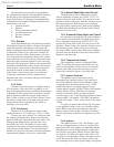
pressure may be adjusted. Remove the 1/8 NPT plug
from the lower side of the gas valve that is to be set
and install a tting, hose and manometer. Start the
appliance and observe the manifold pressure. Manifold
pressure must be adjusted to 3.0 in. W.C. (0.75 kPa)
(for high altitude only, standard operating pressure is
2.5 in. W.C. (0.62 kPa)). It is adjusted by removing the
slotted cap on the gas valve and turning the adjustment
screw (beneath the cap) clockwise to increase
pressure and replaced after the adjustments have been
completed and the tting, hose and manometer have
been removed and the 1/8" plug has been replaced.
Repeat this process until all gas valves have been set.
Note: The pressure can be set only when the appliance
is operating and only when the particular gas valve
being adjusted is energized by a call for heat from the
staging control.
After all of the gas valve manifold pressures
have been set, the CO
2
or O
2
must be reset. CO
2
or O
2
will have changed when the manifold pressure was
adjusted. Open the air shutter(s) to reduce the CO
2
or
O
2
to the values achieved previously.
The procedure is complete when all gas valves
are adjusted to a manifold pressure of 3.0 in. W.C.
(0.75 kPa) and the CO
2
is adjusted to 8.0% for Natural
Gas appliances or 9.2% for LP appliances. When using
an O
2
analyzer, the correct O
2
is 6.8% for both Natural
Gas and LP appliances.
Caution
Should any odor of gas be detected, or if the gas
burner does not appear to be functioning in a
normal manner, close main shutoff valve, do not
shut off switch, and contact your heating contractor,
gas company, or factory representative.
6.5 Shutting Down the Copper Brute II
1. Switch off the main electrical disconnect switch.
2. Close all manual gas valves.
3. If freezing is anticipated, drain the heater and be
sure to also protect building piping from freezing.
This step to be performed by a qualied
service person.
6.6 To Restart the Copper Brute II
If drained, follow Section 6.1 in this manual for
proper lling and purging.
1. Switch off the main electrical disconnect switch.
2. Close all manual gas valves.
3. WAIT FIVE (5) MINUTES.
4. Set the aquastat or thermostat to its lowest
setting.
5. Open all manual gas valves.
6. Reset all safety switches (pressure switch,
manual reset high limit, etc.).
7. Set the temperature controller to the desired
temperature setting and switch on electrical
power.
8. Burner will go through a prepurge period and
ignitor warm-up period, followed by ignition.
SECTION 7.
Maintenance
7.1 System Maintenance
1. Lubricate the system water-circulating pump, if
required, per the instructions on the pump.
2. If a strainer is employed in a pressure reducing
valve or the piping, clean it every six months.
3. Inspect the venting system for obstruction or
leakage at least once a year. Periodically clean
the screens in the vent terminal and combustion
air terminal (when used).
4. Keep the appliance area clear and free from
combustible materials, gasoline, and other
ammable vapors and liquids.
5. If the appliance is not going to be used for
extended periods in locations where freezing
normally occurs, it should be isolated from the
system and completely drained of all water. All
systems connected to it should also be drained or
protected from freezing.