


Internet Version for Reference Only
Bradford White
Page 32
Copper Brute II
Page 33
The gas and electric controls on the appliance
are engineered for long life and dependable operation,
but the safety of the equipment depends on their
proper functioning. It is strongly recommended that
a qualied service technician inspect the basic items
listed below every year.
a. Ignition controls
b. Ignitors
c. Water temperature control
d. Automatic gas valve
e. Pressure switches
f. Blowers
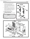
7.2.1 Burners
Close main manual gas valve before proceeding.
Checking the burners for debris - Remove the ignitor
inspection panels(s) and ignitor(s) and inspect the
burners through the ignitor hole(s) using a ashlight
to illuminate. If there is any indication of debris on
the burners that are visible, all the burners will need
to be inspected more thoroughly. Remove the screws
from around the front of the air box (large panel from
which the ignitor inspection panel(s) were removed),
and remove the large panel. Remove the gas manifold
assemblies and the burner panels. Inspect the burners.
Clean burners, if necessary, by blowing compressed
air from the outside of the burners into the center
of the burner. A dirty burner may be an indication
of improper combustion or dirty combustion air.
Determine the cause, and correct. Replace the burners
in the reverse order
7.2.2 Filter
The lter used in the heater is washable with an
83% arrestance. Since the lter is washable, it will
only need replacement when unwashable, deteriorated
or damaged. If lter replacement is needed, it should
only be replaced with a factory part. Inspect the air
lter. If there is debris on the air lter, remove it from
the lter box, and wash it with mild soap and water.
Ensure that the lter is completely dry before re-
installing, in reverse order.
7.2.3 Gas Valves
The gas valves are designed to operate with
supply pressures of 4-13 inches w.c. (1.0 to 3.2 kPa).
To remove a valve, shut off 120-volt power and
the manual gas shutoff valve. Remove the top front
panel from the unit. Disconnect the wires to the valve.
Disengage the anges before and after the valve,
and remove the valve. Re-install in reverse order,
ensuring that the gasket o-rings are placed properly
in the grooves on the anges. Turn on manual gas
shutoff valve and 120 volt power and check appliance
operation and tightness of gas valve connections.
7.2.4 Manual Reset High Limit Control
The high limit switch is manual reset switch
with an adjustable set point, up to 200°F (93°C). To
replace the switch, shut off the 120-volt power to the
appliance. Remove the cover from the switch to access
the mounting screws. Remove the screws, and pull
the switch off the control panel. Remove the capillary
and bulb from the thermal well located in the header.
Replace in reverse order.
7.2.5 Automatic Reset High Limit Control
An automatic reset high limit is used in addition
to the manual reset high limit. The high limit switch
has an adjustable set point, up to 200°F (93°C). To
replace the switch, shut off the 120-volt power to the
appliance. Remove the cover from the switch to access
the mounting screws. Remove the screws, and pull
the switch off the control panel. Remove the capillary
and bulb from the thermal well located in the header.
Replace in reverse order.
7.2.6 Temperature Control
The temperature control is a Bradford White
LHSC. To replace the control, shut off the 120-volt
power to the appliance. Remove the cover from the
control panel, and remove the mounting screws to
remove the controller. Replace in reverse order.
7.2.7 Ignition Controls
The ignition controls ensure the proved
interrupted-type ignition system. They control the
hot surface ignitors and prove that the ame signal
is appropriate for powering the gas valves. It also
controls the blower’s pre-purge and post-purge.
Copper Brute II models 500 and 750 have one ignition
control. Models 1000 to 2000 have two ignition
controls. On models 1000, one ignition control
controls stages 1 and 2, and the second ignition control
controls stage 3. On models 1250-2000, one ignition
control is for stages 1 and 2, and the other is for stages
3 and 4.
To replace a control, shut off the 120-volt power
to the appliance. Remove the cover from the control
panel. Remove the electrical connectors from the
ignition control. Take out the controller’s mounting
screws, and pull the controller out. Replace in reverse
order.
7.2.8 Ignitors
The ignitors used are 120v “Hot Surface” type.
They are energized whenever there is a call for heat
and switched off when ignition is established and the
ame has been sensed. Copper Brute II models 500
and 750 have one ignitor. Models 1000 to 2000 have
two ignitors. To replace the ignitor, shut off the 120-
volt power to the appliance, remove the ignitor access
panel, disconnect the Molex connector, remove the
two mounting screws on the ignitor ange, and pull the