


Internet Version for Reference Only
Bradford White
Page 36
Copper Brute II
Page 37
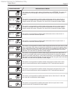
8.6 Troubleshooting Copper Brute II
Controls
The Copper Brute II series consists of two 2-
stage models (500 and 750), one 3-stage model (1000),
and four 4-stage models (1250 to 2000). The 2-stage
models have one ignition module, and the 3- and
4-stage models have two ignition modules capable of
independent operation.
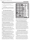
A diagnostic panel, that includes test points, as
well as diagnostic lights, is provided in the control
module. It is located on the right side of the module,
behind the display. To access, remove the retaining
screws from the display cover panel and remove
it. Grasp the control module at its base and pull it
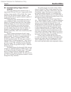
outward. Ladder diagrams are shown in Figures 18
through 20. Voltage test points on the diagnostic
panel are indicated by solid circles connected by short
diagonal lines.
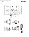
Figure 18 shows the diagram for the 2-stage
models 500 and 750. These have one blower and one
ignition module. The blower is energized directly
through the “inducer” terminals F1 and F2 of the
(Fenwal) ignition module. The 24V power to the 2
nd
stage gas valve is routed through the 1
st
stage VALVE
terminal, so that stage 2 cannot re unless the stage 1
gas valve is open. The 750 differs from the 500 only
in that the 750 has two gas trains in stage 1, while the
500 has only one.
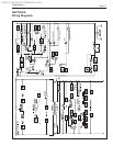
The ladder diagram for the model 1000 is shown
in Figure 19. Ignition module #1 handles stages 1 and
2, and ignition module #2 handles stage 3. The single
blower is energized directly through the “inducer”
terminals of either ignition module. The 24V power to
the T’STAT terminal of both ignition modules is routed
through the safety interlocks.
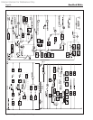
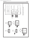
The ladder diagram for models 1250 to 2000 is
shown in Figure 20. These 4-stage models have two
ignition modules, each with its own blower, and each
controlling 2 stages. The blowers are energized by
the ignition modules indirectly via switching relays.
When either ignition module receives a call for heat, it
switches its blower to high speed and the blower of the
idle ignition module to low speed.
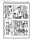
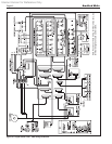
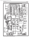
The wiring schematics for the Copper Brute II
500 – 1000 are shown in Figure 21, and the schematics
for the 1250 to 2000 are shown in Figure 22. All 24V
wiring is routed through the diagnostic PC board.
Wiring harnesses connect between the diagnostic PC
board and the control components, indicator board,
or eld wiring terminal strip. The diagnostic board
contains LEDs that indicate open status of the safety
interlocks, and quick-connect terminals that provide
tests points for checking voltage/continuity at various
points in the control circuit. Line-voltage connections
are routed via the line-voltage terminal buss.
Certain control elements that may need to be
re-wired in the eld are connected via the eld wiring
terminal strip rather than to the diagnostic PC board.
These include the low-water cutoff (LWCO), water
ow switch, and inlet/outlet water temperature sensors.