


Internet Version for Reference Only
Bradford White
Page 24
Copper Brute II
Page 25
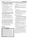
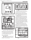
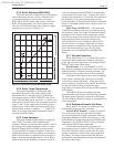
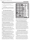
Step 3: Press the three programming buttons to
enter “ADJUST” mode (Figure 10). Press “Item” to
select the programming item, and the arrow keys to
adjust the setting. See section 6.2 Programming the
Temperature Control if more programming instructions
are needed.
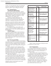
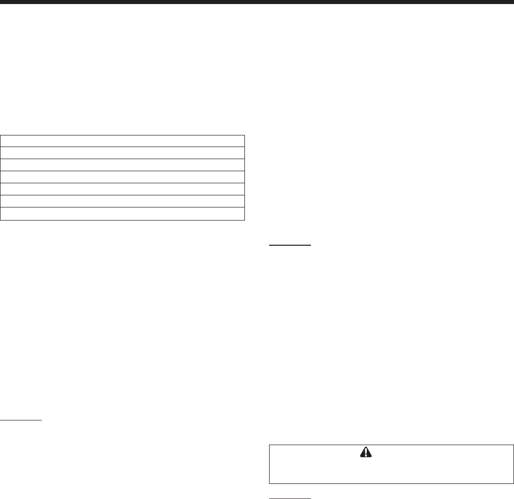
Recommended settings for hydronic system with
180°F / 83°C primary loop temperature:
Item F° C°
MODE 2 2
BOIL TARGET 180 83
BOIL MASS 1 1
DIFF 20 10
DLY 5:00 5:00
F° F° °C
Step 4: See section 6.3.11 Limit Controls. Set
both high limit controls at least 25°F / 14°C higher
than the BOIL TARGET to allow for temperature rise
across the heat exchanger.
6.2.4 Choosing the Mode for your
Application
This section describes various applications and
the recommended eld wiring and Mode selections.
Water heater systems with Copper Brute II
heater(s) and tank(s) will almost always use either
mode 1 or mode 3. All other modes are for boiler
applications. These modes are described in this
manual for completeness, since they are accessible
in the water heater control software.
Mode 1: Heater operates using its own inlet
and outlet sensors only, not relying
on a remote thermostat, aquastat,
or external sensor.
This setup is most commonly found in domestic
hot water applications with a continuous run pump.
This is not recommended for other applications.
The heater is shipped with a jumper between the
“Com D” and “Ht D” terminals, which must remain
in place to allow the unit to re. The unit will re
whenever the outlet temperature cools below the target
temperature.
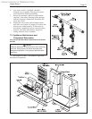
Important Note: If the heater is pump-mounted
at the factory, or if a eld-supplied pump contractor
is connected to the heater’s pump contactors (Pmp
Pmp), the user must program the controller’s pump
delay (DLY) setting to ON. When ON is selected,
pump operation is continuous. The unit’s inlet and
outlet sensors must be able to detect the temperature
in the storage tank in order to control it. Without the
tank water continuously running through the heater,
the heater will have no way of knowing what the
temperature in the tank is, and will not be able to
respond to a change in tank temperature. Short cycling
or lack of hot water may result if the pump does not
run continuously.
Mechanical aquastat in a domestic hot
water storage tank.
Remove the jumper from the “Com D” and
“HtD” terminals and connect the aquastat’s leads to
these terminals. This connection uses a standard, non-
powered mechanical aquastat. When the aquastat calls
for heat, the heater’s temperature control will respond
and start the heater pump (if equipped) and re the
heater.
If the heater is not a pump mounted model, a
24VAC pump contactor may be connected to the
“PMP” terminals to control a eld installed pump.
(If desired, the pump can run continuously, with the
aquastat telling the heater when to re.)
Program the temperature control to use “Mode
1.” The AUTO/MAN switch must be in the AUTO
position in this mode.
Mode 3: Bradford White R2014800 sensor
installed in the domestic hot water
storage tank.
The heater ships with a jumper between the
“Com D” and “Ht D” terminals. Verify this jumper is
in place, and connect the sensor leads to the “S C2”
and “SUP S” terminals. When the sensor detects a
temperature below the target temperature, the control
will respond and start the heater pump (if equipped)
and re the heater.
If the heater is not a pump mounted model, a
24VAC pump contactor may be connected to the
“PMP” terminals to control a eld installed pump. (If
desired, the pump can run continuously).
Program the temperature control to use “Mode
3.” The AUTO/MAN switch must be in the AUTO
position in this mode.
Caution
If the tank temperature control is set too high, a
potential for hot water scalding may exist.
Mode 2: Primary secondary piping.
Install a “supply sensor” in the primary loop
using the Bradford White part number R2014800
sensor (included with every unit). Connect the sensor
to the “S C2” and “SUP S” terminals.
You must provide an indication of the system’s
heat demand by removing the jumper across the
“ComD” and “HtD” terminals on the eld wiring
panel and connecting a zone valve or zone pump end
switch, thermostat, aquastat or other contact closure to
these terminals. If the “ComD” and “HtD” terminals
are left jumpered, the control will always see a heat
demand and remain in “Dem” mode, with the boiler
pump running continuously. See Section 5.2 for more
information.
A secondary aquastat, such as for a separate heat
exchanger for DHW, can be connected to the “Set D”
and “Com D” terminals. A call for heat from these
controls will start the boiler pump and cause the heater
to re.