


Internet Version for Reference Only
Bradford White
Page 20
Copper Brute II
Page 21
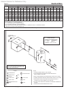
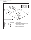
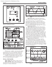
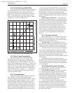
Most of the time, the number of stages from the
external control will match the number of stages on the
heater. However, in some instances, the controller will
not have enough staging capability to work with all of
the stages on a heater (for instance, using an 8-stage
external control with four 4-stage Copper Brute II
units.) In these instances, it is very important to follow
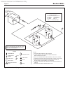
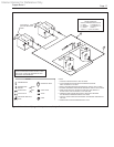
the instructions in this section. Figure 9 shows how to
combine stages on the heater for those instances when
the external controller cannot control all the stages
available on the heater.
Note: The only time heater stages should be
jumpered is when the heater has an external control,
and the heater is used in Mode 6. In all other modes,
when the heater controls its stages, the terminals
shown in Figure 9 must NOT be jumpered.
SECTION 6.
Operating Instructions
6.1 Sequence of Operation
A call for heat can be initiated either
automatically (“auto mode”) under thermostatic
control by the heater temperature control, or by an
external contact closure (“manual mode”).
In auto mode, the heater will re its stages of
input to maintain a target temperature programmed
into the temperature control. The controller can be
programmed per section 6.2.
In manual mode, an external control will control
the heater stages, as long as the heater control is set to
mode 6, and the auto/manual switch (located inside the
control compartment) is set to manual.
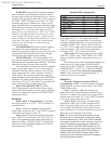
The amber “Ready” light on the front panel
indicates that the control system is energized. Upon a
call for heat, the green “Heat” indicator on the front
panel will light.
If the unit is pump-mounted, the pump will be
energized. The pump terminals on the eld-wiring
terminals strip will energize a eld pump that is
properly interlocked with the heater. The green
“Pump” indicator on the front panel will light.
Once the water ow switch makes, and if all of
the safety interlocks are closed, the ignition module
will energize the blower(s) for a 15-second pre-purge,
followed by a 20-second period to allow the ignitor to
heat.
Energizing the blower pressurizes the air box
(which supplies air to the burners) and closes the
normally-open contact(s) of the airow pressure
switch(es). This allows the ignition module to proceed
with the ignition sequence.
The blocked ue pressure switch senses the
pressure in the plenum. It will interrupt the airow
sensing circuit if this pressure exceeds a maximum
value. If airow is not proven, the ignition module
will lockout.
The ignition module checks that the ignitor
current has reached a minimum value and energizes
the gas valve at the end of the ignitor heating period.
The green “Stage 1” indicator on the front panel will
light, indicating that the stage 1 gas valve is open.
After a 4-second trial for ignition, the ignitor
switches off, and unless a ame is detected by the
ame sensor, the gas valve will close and the ignition
module will either attempt ignition again (up to three
times) or will lockout (if the optional lockout ignition
module is used).
If ame is sensed, the burner will continue to
re as long as there is a call for heat. In Auto mode,
additional stages are delayed by a minimum of 60
seconds (less prepurge and ignitor warm-up time) and
once energized, must re for at least 30 seconds. The
request for additional stages is indicated on the control
display, and the energizing of additional burner stages
is indicated by front panel lights.
If there is a subsequent loss of ame signal, the
burner will attempt re-ignition up to three times (only
once if optional lockout ignition module is used.)
When the call for heat is satised, the gas
valve(s) closes and the blower(s) continues to run
for 30 seconds. The pump will continue to run for a
minimum of 20 seconds and up to a programmable
maximum of 10 minutes.
If a call for heat is prevented from being satised
either by a safety interlock or due to an ignition
lockout, the red “Service” indicator on the front panel
will light. To reset the standard ignition module,
the reset button on the module must be pressed.
Interrupting power to this module will not reset the
lockout.
The Copper Brute II 1000 - 2000 models have
two ignition modules that control different burners. If
one module should fail for any reason, the remaining
module can operate its burner(s) independently.
Important: The installer is responsible for identifying
to the owner/operator the location of all emergency
shutoff devices.
WARNING
Do not use this appliance if any part has been
under water. Immediately call a qualied service
technician to inspect the appliance
and to replace any part of the control system and
any gas control that may have been
under water.
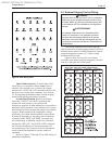
6.2 Programming the Temperature
Control
The same temperature control is used on all
versions of the Copper Brute II (in two-and four-stage
congurations), providing maximum exibility to meet
the needs of any system. Before start-up, you must
program the temperature control for the type of system