


Internet Version for Reference Only
Bradford White
Page 22
Copper Brute II
Page 23
The rst item is “Mode”; enter the mode number
as determined above. The Temperature Control will
then present you with some or all of the following
options, depending on the mode you have chosen:
In mode 6, external heater control, you will not
see the following options. Refer to manual, section
6.3.10, for setup information for mode 6.
FOR ALL OTHER MODES:
BOIL MASS (Boiler Mass): Always choose “1”.
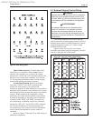
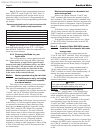
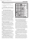
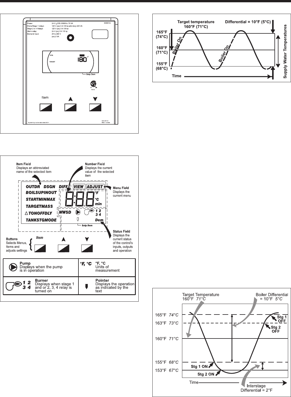
BOIL TARGET (Boiler Target Temperature):
Your desired set-point temperature. See section 6.3.5
and Figure 12 for more information.
Figure 12. Temperature Control Target Temperature
Graph.
BOIL MIN (Boiler Minimum Temperature):
This setting tells the Temperature Control to maintain
at least this temperature, even if the PID logic
determines a lower setting would save energy. The
BOIL MIN should always be 120°F (49°C) or higher
to prevent condensation, and can be set up to 10°F
below your BOIL TARGET temperature. See section
6.3.3 for more information.
BOIL MAX (Boiler Maximum Temperature):
This setting tells the Temperature Control to limit the
maximum outlet temperature to this setting or below,
and determines how quickly the temperature control
“stages down” or off. If the BOIL MAX setting is
much higher than the BOIL TARGET temperature, the
temperature control will re all stages until the target
temperature is reached, and then shut down all stages
at once. To enable gradual staging down of the heater
as you approach your target temperature, set the BOIL
MAX to the same setting as the target temperature. See
section 6.3.4 for more information.
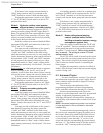
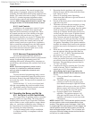
DIFF (Differential): This setting is divided
above and below the target temperature. The water
will be allowed to cool this setting below the target
temperature before rst stage res, and will heat to
this setting above the target temperature before staging
the heater down. See Section 6.3.1 and Figures 12 and
13 for more information.
Figure 13. Temperature Control Interstage Differential
Graph.
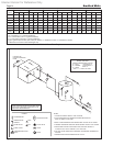
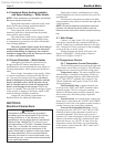
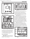
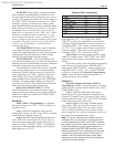
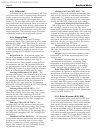
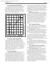
Figure 10. Temperature Control.
Figure 11. Temperature Control Symbol Description.