


Internet Version for Reference Only
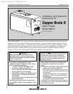
Bradford White
Page 6
Copper Brute II
Page 7
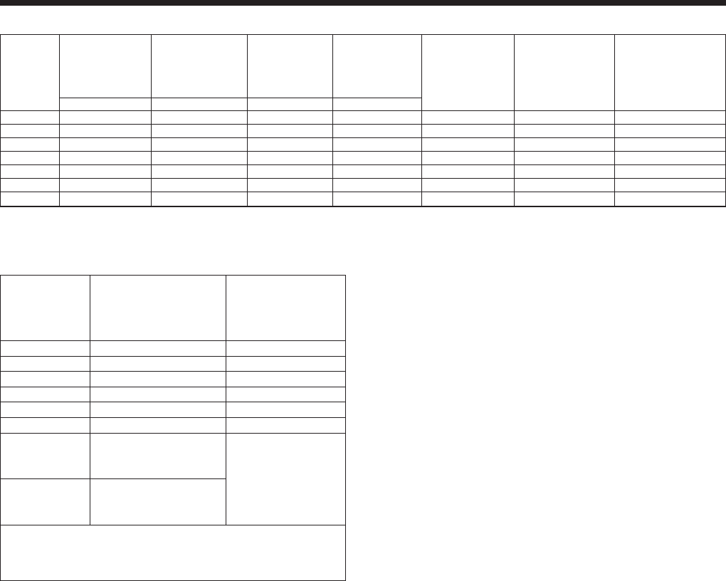
Required Recommended
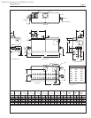
Appliance Clearance From Service Access
Surface Combustible Material Clearance
inches cm inches cm
Left Side 1 2.5 24 61
Right Side 1 2.5 24 61
Top 1 2.5 12 30
Back 1 2.5 **12** 30**
Front 1 2.5 36 91
Vertical
(Category 1) 6* 15.2*
Vent
Horizontal per UL1738 venting
(Category 3) system supplier’s
Vent instructions
*1" (2.5cm) when b-vent is used.
**When vent and/or combustion air connects to the back,
recommended clearance is 36" (91cm).
Table 2. Clearances.
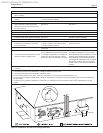
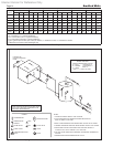
1.6 Locating Pump-Mounted Water Heater
with Respect to Storage Tank(s)
For best results, a pump-mounted water heater
should be located within 15 feet (4.6m) of the storage
tank(s). The pump is sized for 30 feet (9.1m) of piping.
If the heater must be installed with longer piping
runs, then larger diameter pipe or tubing shall be used.
Consult the factory for assistance.
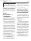
1.7 Locating Appliance for Correct
Horizontal Vent/Ducted Air Distance
From Outside Wall
The forced draft combustion air blower/blowers
in the appliance has/have sufcient power to pull air
and vent properly when the following guidelines for
horizontal air and vent are followed (see Table 1).
NOTE: On models 750-2000, the vent collar size is
larger than the size of the vent pipe that can be used.
Vent collar size and horizontal pipe diameters can
be found in Table 1. The larger vent collar size is to
accommodate Category I (vertical) vent systems.
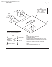
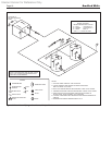
NOTE: When located on the same wall, the
combustion air intake terminal must be installed
a minimum of 12" (30cm) below the exhaust vent
terminal and separated by a minimum of 36 inches
(91cm) horizontally.
The air intake terminal must be installed high
enough to avoid blockage from snow, leaves and other
debris.
SECTION 2.
Venting and Combustion Air
2.1 Combustion Air
Copper Brute II water heaters must have
provisions for combustion and ventilation air in
accordance with section 5.3, Air for Combustion and
Ventilation, of the National Fuel Gas Code, ANSI
Z223.1, or Sections 7.2, 7.3 or 7.4 of CSA B149.1,
Installation Codes, or applicable provisions of the local
building codes.
A Copper Brute II heater may receive
combustion air from the space in which it is installed,
or it can be ducted directly to the unit from the outside.
Ventilation air must be provided in either case.
2.1.1 Combustion Air From Room
In the United States, the most common
requirements specify that the space shall communicate
with the outdoors in accordance with method 1 or 2,
which follow. Where ducts are used, they shall be of
the same cross-sectional area as the free area of the
openings to which they connect.
Method 1: Two permanent openings, one
commencing within 12 inches (30 cm) of the top
and one commencing within 12 inches (30 cm) of
the bottom, of the enclosure shall be provided. The
openings shall communicate directly, or by ducts,
with the outdoors or spaces that freely communicate
with the outdoors. When directly communicating
with the outdoors, or when communicating to the
outdoors through vertical ducts, each opening shall
have a minimum free area of 1 square inch per 4000
Btu/hr (5.5 square cm/kW) of total input rating of all
equipment in the enclosure. When communicating to
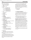
Horizontal Air Collar
Heater Vent Collar Vent Pipe & Pipe Max. Pipe Max. No. Side Wall Side Wall
Size Size Diameter Diameter Length of Elbows Vent Combustion
Terminal Air Terminal
in. cm in. cm in cm ft. m Part Number Part Number
500 6 15 6 15 6 15 50 15 3 CA001401 20260701
750 8 20 6 15 6 15 50 15 3 CA001401 20260701
1000 10 25 8 20 8 20 50 15 3 CA001402 20260703
1250 12 30 8 20 8 20 50 15 3 CA001403 20260703
1500 12 30 8 20 8 20 50 15 3 CA001403 20260703
1750 14 36 8 20 8 20 50 15 3 CA001403 20260703
2000 14 36 12 30 12 30 50 15 3 CA001404 20260706
Table 1. Horizontal Vent / Combustion Air Parameters.