


Internet Version for Reference Only
Bradford White
Page 20
Copper Brute II
Page 21
you have. You must determine the type of piping the
system has, the Mode the temperature control will
operate in, and the various settings for that mode.
6.2.1 System Piping
“Primary Secondary Piping”
In the context of these instructions, “primary
secondary piping” means the heater provides heat to a
plumbing loop that has, in turn, one or more plumbing
loops connected to it, which provide heat to radiant
tubing, radiators, DHW heat exchangers, etc. This
plumbing loop is the “primary loop.”
In primary secondary piping modes, the
temperature control monitors the primary loop
temperature. The extra sensor that is shipped loose
with heater is installed in the primary loop. The
temperature control res the heater stages to provide
the “target temperature” at that sensor. Over time, the
temperature control will learn the system curve and
adjust the ring of the stages to meet the demand in
the most efcient way.
For complex systems, with variable speed
injection circulators, multiple temperature zones, etc.,
you may need to consult with a qualied engineer or
Bradford White.
“Parallel Piping”
The term “parallel piping” means the heater is
supplying heat directly to one or more storage tanks,
radiators, radiant zones, etc., plumbed in series. In
these systems, the target temperature is the heater’s
outlet temperature. An exception is for domestic hot
water systems using mode 3, where the extra sensor is
placed in the tank.
6.2.2 Choosing the Mode
There are six modes of operation for the heater's
temperature control. The loose sensor must be installed
and connected prior to programming the temperature
control, as it provides sensing the “target” temperature.
The location of the sensor is dependent on the type of
piping used.
Modes 1 through 5 are the automatic modes,
requiring the diagnostic panel’s AUTO/MAN switch
(located on the slide-out control drawer) to remain in
the default “AUTO” position. These modes enable the
temperature control to re the heater’s stages to meet
the demand of the system. In these modes, the heater's
temperature control continuously samples the inlet,
outlet and target temperatures.
Mode 6 is the “Manual” mode, and the AUTO/
MAN switch must be moved to the “MAN” position.
An external control, such as a building automation
system or multiple heater control, just be wired to the
eld wiring panel in order to re the heater, bypassing
the temperature control. (See Section 5.3 for important
information about external staging controls and
building automation systems.)
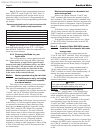
Application Mode System
Setting Sensors Used
• Parallel piping (non-
primary/secondary)
hydronic system 1 • None
• DHW with or without
a tank aquastat
• Primary/secondary
hydronic system 2 • Bradford White System
(preferred by Sensor (shipped with
Bradford White) each Copper Brute II)
• No outdoor reset
• Parallel piping (non-
primary/secondary)
hydronic system 3 • Bradford White System
• DHW Sensor (shipped with
• Advanced control each Copper Brute II)
capability
• No outdoor reset
• Parallel piping (non- • Bradford White outdoor
primary/secondary) reset sensor (optional
hydronic system 4 part #R2014000)
• Advanced control
capability
• Outdoor reset
• Primary/secondary • Bradford White System
hydronic system 5 Sensor (shipped with
(preferred by each Copper Brute II)
Bradford White)
• Outdoor reset •Bradford White outdoor
reset sensor (optional
part # R2014000)
• Building automation
control
• Multiple boiler system 6 • None
control
• Energy management
system
• Other external control
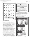
Table 9. Modes and Sensors for Applications.
Table 9 contains information to identify the mode
you should use for your system.
6.2.3 Programming
Before programming, you must determine the
type of piping you have, the mode you will use, and
install the extra sensor if required for that mode. See
sections 6.2.1 and 6.2.2 for more information, or
contact the factory.
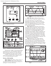
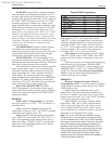
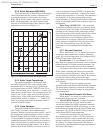
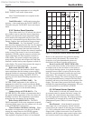
There are three black programming buttons on
the Temperature Control (see Figures 10 and 11). Press
and hold all three programming buttons until the word
“ADJUST” appears in the upper right corner of the
LCD display (it replaces the word “VIEW”).
Pressing “Item” cycles you through the items
you need to program. “Up Arrow” increases the
value of that item, while “Down Arrow” decreases it.
“ADJUST” mode exits if you don’t press a button for
20 seconds. To return to “ADJUST” mode, simply
press and hold the three buttons again.