


Internet Version for Reference Only
Bradford White
Page 32
Copper Brute II
Page 33
ignitor out. Install in reverse order, always using a new
ignitor gasket with the replacement ignitor.
Caution
Ignitor gets hot.
7.2.9 Ignition Sensors
The ignition sensors ensure that the main ame
is ignited, so that raw gas is not allowed to ll the
combustion chamber. Copper Brute II models 500 and
750 have one sensor. Models 1000 to 2000 have two
sensors (one for each ignition control). The ignitors
are the ignition sensors on the heater. There are no
separate ignition sensors.
7.2.10 Transformer
The Copper Brute II’s transformer is not capable
of supplying control voltage for external devices such
as zone valves, which must have their own separate
power supply. Should a transformer need replacing,
shut off the 120-volt power. Unplug the transformer
wires, remove the mounting screws and remove the
transformer. Replace transformer in the reverse order.
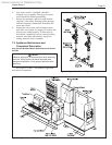
7.2.11 Blowers
The combustion air blowers bring the
combustion air for the heater from the upper chamber
to the lower chamber. Mixing of the gas and air occurs
in the burners. Models 500, 750 and 1000 each have
one blower, and models 1250 to 2000 each have two
blowers (one blower for stages 1 and 2, and one for
stages 3 and 4). If a blower change is required, turn off
the 120-volt power and gas supply to the unit. Remove
the front panel. Disconnect the blower's wire harness.
Remove the screws at the blower ange, and pull the
blower out. Replace blower in reverse order, ensuring
that all joints are made correctly. After replacement,
ensure that the unit operates properly, by following the
set-up procedure in this manual.
7.2.12 Flow Switch
The heater uses a paddle-type ow switch to
ensure that the unit has water ow before ignition is
allowed.
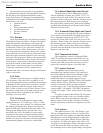
7.2.13 Heat Exchanger Coil
WARNING
Black carbon soot buildup on a dirty heat exchanger
can be ignited by a random spark or ame, thereby
creating a risk of re or explosion.. To prevent this
from happening, dampen the soot deposits with a
wet brush or ne water spray before servicing the
heat exchanger.
The heater has a pre-mixed burner system. These
systems provide the burners with sufcient air for
complete combustion, and black carbon sooting is
seldom experienced. If sooting is suspected, view ports
for inspection of the heat exchanger are provided on
both sides of the heater. They are located below the
headers, and are accessed by opening the small round
cover that is attached by one screw. In the unlikely
event that there is a buildup of black carbon soot
or other debris on the heat exchanger, clean per the
following:
1. Disconnect the electrical supply to the unit.
2. Turn off the gas supply by closing the manual gas
valve on the heater.
3. Disconnect and remove the wires, conduit and
sensors from all components that are attached to
the inlet/outlet header.
4. Isolate the heat exchanger from the water supply.
5. Disconnect the header anges from the inlet and
outlet.
6. Allow the heat exchanger to drain. Remove the
front cover(s) by removing the rubber access
strip(s) and the retaining screws. Remove the
venting and remove the top, by removing the
screws that attach the top to the side panels.
Remove the side panels. Remove the front lower
panels sealing the combustion area. To remove
the gas train, disconnect the unions located
below the intermediate pan and the eld installed
union located outside the cabinet, and pull up,
bringing the union end connectors through the
grommets in the intermediate pan. To remove the
intermediate pan, remove the slide out control
assembly and blower(s) to reveal the screws.
Remove the screws holding the intermediate pan,
and lift up to remove it. The heat exchanger has
integral metal sections attached, which connect
to the frame of the heater. Locate and remove
the screws along the front, rear and bottom of
the integral metal sections, and remove the heat
exchanger and metal sections by lifting up. On
the larger appliances, a center heat exchanger
support must be unbolted before it can be
removed.
7. Remove the heat exchanger from the unit.
NOTE: The heat exchangers are heavy and may
require two people to remove to avoid personal
injury.
8. Clean the heat exchanger: A light accumulation
of soot or corrosion on the outside of the heat
exchanger can be easily removed. Use a wire
brush to remove loose soot and scale from the
heat exchanger. Do not use water or compressed
air for cleaning.
9. NOTE: While the heat exchanger is out of the
unit, inspect the rewall refractory insulation.
Replace if necessary.