


Internet Version for Reference Only
Bradford White
Page 18
Copper Brute II
Page 19
5.3 External Staging Control Wiring
WARNING
Improper eld wiring may result in re or explosion
which can cause property damage, severe injury,
or death. Make only wiring connections which are
in accordance with the Installation and Operation
manual.
AVERTISSEMENT
Un câblage incorrect lors de l’installation peut
causer un incendie ou une explosion pouvant
entraîner des dommages matériels, de graves
blessures ou la mort. Ne faire seulement que les
connexions conformes au Manuel d’installation et
d’exploitation.
The wiring methods in this section must be
used to connect an external staging control, such as a
multiple heater control, building automation system,
energy management system, etc.) Other wiring
methods may be unsafe.
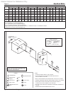
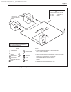
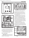
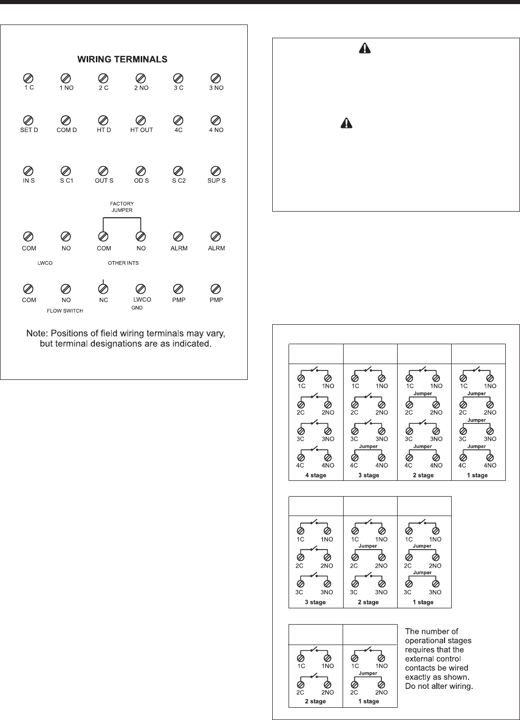
Figure 9 shows how to wire the external
controller to the heater’s eld wiring panel, which is
located on the right side of the heater.
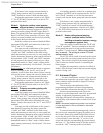
Figure 8. Field Wiring Panel
Other Field Interlocks: To install other eld-
wired devices to interlock with the heater (louver
switches, ow switches, etc.), remove the jumper
between the “COM” and “NO” terminals and wire the
device in series across these terminals. (See Section
5.3 for important information about external staging
controls and building automation systems.)
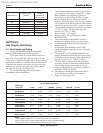
System Heat Demand: Remove the jumper
across the “COM D” and “Ht D” terminals, and
connect the zone pump or valve end switch,
thermostat, aquastat, or other indication of system heat
demand to these terminals. If no indication of a system
heat demand will be provided, the jumper must remain
in place. When jumpered, the temperature control
will always see a heat demand, and the Copper Brute
II pump (if equipped) or any pump with its contactor
connected to the “PMP” and “PMP” terminals will
run continuously. In addition, any device connected
through the “HT OUT” and “LWCO GND” terminals
for an external indication of the heat demand will
run continuously. See section 6 for more information
on the system heat demand for various modes of
operation.
Refer to Figures 23 through 25 for eld wiring of
additional components.
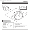
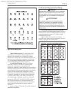
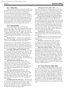
Figure 9. External Control Connection Wiring.
Model 1250, 1500, 1750 & 2000 (4-Stage Heater)
4 stage heater
using 4 control
output
s
4 s
tage heater
using 1 control
output
4 stage heater
using 2 control
output
s
4 s
tage heater
using 3 control
output
s
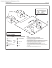
Model 1000 (3-Stage Heater)
3 stage heater
using 1 control
output
3 stage heater
using 2 control
output
s
3 s
tage heater
using 3 control
output
s
Model 750 & 500 (2-Stage Heater)
2 stage heater
using 1 control
output
2 stage heater
using 2 control
output
s