


Internet Version for Reference Only
Bradford White
Page 10
Copper Brute II
Page 11
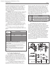
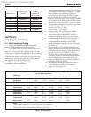
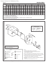
the vent pipe. Horizontal runs must slope downwards
not less than inch per foot (2 cm/m) from the unit to
the vent terminal. Reference Table 1 for the size of the
Category III vent system. Up to three elbows can be
used with 50 linear feet (15.2m) of pipe. Subtract 10
allowable linear feet (3.0m) for every additional elbow
used.
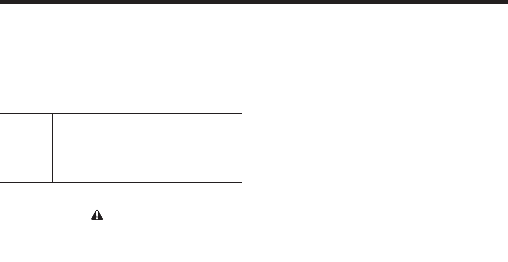
Term Description
Pipe Must comply with UL Standard 1738
such as Type 29-4C Stainless Steel
(either insulated or non-insulated).
Joint Follow vent manufacturer’s instructions
Sealing
Table 5. Required Horizontal Venting Material.
WARNING
The outdoor vent terminal gets hot. Unit must be
installed in such a way as to reduce the risk of
burns from contact with the vent terminal.
2.3 Locating Vent & Combustion Air
Terminals
2.3.1 Side Wall Vent Terminal
The appropriate Bradford White side wall vent
hood must be used, and is listed in the installation and
operation manual. The terminal provides a means of
installing the vent piping through the building wall,
and must be located in accordance with ANSI Z223.1/
NFPA 54 and applicable local codes. In Canada, the
installation must be in accordance with CSA B149.1 or
.2 and local applicable codes. Consider the following
when installing the terminal:
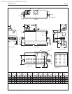
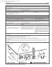
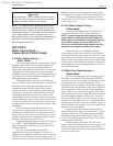
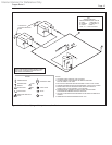
1. Figure 3 shows the requirements for mechanical
vent terminal clearances for the U.S. and Canada.
2. Vent terminals for condensing appliances or
appliances with condensing vents are not
permitted to terminate above a public walkway,
or over an area where condensate or vapor could
create a nuisance or hazard.
3. Locate the vent terminal so that vent gases cannot
be drawn into air conditioning system inlets.
4. Locate the vent terminal so that vent gases cannot
enter the building through doors, windows,
gravity inlets or other openings. Whenever
possible, locations under windows or near doors
should be avoided.
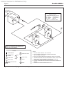
5. Locate the vent terminal so that it cannot be
blocked by snow. The installer may determine
that a vent terminal must be higher than the
minimum shown in codes, depending upon local
conditions.
6. Locate the terminal so the vent exhaust does
not settle on building surfaces or other nearby
objects. Vent products may damage such
surfaces or objects.
7. If the water heater uses ducted combustion air
from an intake terminal located on the same wall,
locate the vent terminal at least 3 feet (0.9m)
horizontally from the combustion air terminal,
and locate the vent terminal at least 1 foot (0.3m)
above the combustion air terminal.
Important Note:
Massachusetts Code Requirement.
For Sidewall Vented Appliances with Vent Ter-
minals Located Less Than 7 Feet above grade:
1. Massachusetts Code requires that a CO Detector
and Alarm, listed by an approved third party
inspection agency to ANSI/UL 2034 and
complying with NFPA720 (2005 Edition) be
installed on each oor level in which there are
bedroom(s), if there is not one already present.
The location shall be in the living space outside
the bedroom(s).
2. An additional CO Detector and Alarm, as
indicated above, shall be located in the room that
houses the appliance and shall be powered by the
same electrical supply as the appliance such that
one service switch serves both the appliance and
the CO detector. The CO detector shall have a
battery backup.
3. The vent terminal, and if applicable the air intake
terminal, shall be the approved Laars terminals.
A copy of this manual shall remain with the
appliance at the completion of the installation.
4. A metal or plastic identication plate shall be
permanently mounted to the exterior of the
building at a minimum height of eight (8) feet
above grade directly in line with the exhaust vent
terminal for the horizontally vented gas fueled
heating appliance or equipment. The sign shall
read, in print size no less than one-half (1/2) inch
in size, “GAS VENT DIRECTLY BELOW.
KEEP CLEAR OF ALL OBSTRUCTIONS”.
For Sidewall Vented Appliances with Vent Ter-
minal Located More Than 7 Feet above grade:
Items 1, 2 and 3 above shall apply. Follow
the Installation Instructions provided with the CO
Detectors when installing them. For issues with the
CO Detectors, contact the installing contractor.
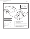
2.3.2 Side Wall Combustion Air Terminal
The Bradford White side wall combustion air
terminal (listed in Table 1) must be used when the
unit takes its combustion air through a duct from a
side wall. Consider the following when installing the
terminal:
1. Do not locate the air inlet terminal near a source
of corrosive chemical fumes (e.g., cleaning uid,
chlorinated compounds, etc.)