


Rev. A.1, 10/99 Page- 7
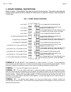
TERMINALS "Y1, Y2, Y3, Y4": These input terminals are only active if the AM option has been supplied.
With the option, a second (yellow) LED will be mounted adjacent to the standard bicolor. When the respective "Y"
terminal receives +V, the yellow LED will illuminate. This is used to annunciate any condition monitored from a dry
contact closure or voltage signal. Most commonly, the yellow LED annunciates the beginning of delayed exit for a
door but other purposes are possible.
TERMINAL "AY": This is a +V voltage output that is on when any Y terminal is on (illuminating the yellow
LED). It is active only when the AM option is supplied. It is prewired to drive a pulsing Sonalert so that when
any yellow LED illuminates, it will be annunciated with a distinctive sound. With multiple boards in a panel, all AY
terminals wire together with a single wire from any one going to the pulse Sonalert input. If the user wishes to
disable the AY audible alert, this single wire may be cut.
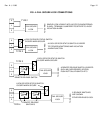
TERMINALS "S1, S2, S3, S4": These input terminals illuminate the green side of the respective zone
bicolor LED when they receive +V. They are connected to lock or door status output such that closed or +V =
secure for the zone. In the normal condition of the panel, the zones are secure, the bicolor LED's show green and
the S terminals receive +V.
TERMINALS "L1, L2, L3, L4": These terminals supply +V when the respective toggle switch is in the on
position (points toward the LED). They are connected to fail safe locks. If fail secure locks are employed, these
terminals are used only when status or remote release switches are present on the zone. The L terminals are used
to power the switch commons.
TERMINALS "E1, E2, E3, E4": These terminals are both an input and an output. When the respective
toggle switch is off (points away from the LED), the terminals supply +V to release a fail secure lock. At the same
time, the yellow indicator in the toggle switch bat illuminates (this annunciates "legal release" of the lock). Also the
violation condition of the zone is shunted. While the lock is legally released (toggle off; bicolor off; toggle bat yellow
LED on), the zone will not violate. As the lock status input (S terminals) reports insecure (since the lock has been
released), the green bicolor indicator will go off but the red side will not come on as would be the case if the
respective E terminal did not have +V on it.
As stated above, turning the toggle off puts +V on the E terminal. The same can be accomplished from a remote
switch. If, for instance, a remote release switch sends power to a fail secure lock, it will "legally" release. This will
input power to the E terminal as it is already connected to the lock. The yellow indicator in the toggle bat will light
up even though the toggle remains in the on position and the violation condition will be shunted.
Annunciating legal release and shunting zone violation is also accomplished with a fail safe lock. The fail safe lock
connects to the L terminal. A remote SPDT switch can legally release it. The common and NC contacts break
power to the fail safe lock, but the NO contact is wired back to the E terminal. When the fail safe lock is therefore
remotely released by this switch, the respective E terminal receives +V and the toggle bat indicator lights up
annunciating the condition and shunting the violation.
4. WIRING
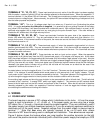
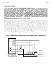
4.1 POWER INPUT WIRING
The board requires a source of DC voltage which it distributes to the locks. +V from the power
supply is input to terminals +1, +2, +3 and +4. If the power supply you are using has a single
DC output, the +1 through +4 terminals should be jumped together. They are individually used if
the power supply has multiple breakered outputs or if you are employing upstream switches to
deactivate any of the panel zones. Negative voltage from the power supply is always input to
terminal “-”. Note that four wires are typically required to be run to each door unless
Securitron’s XDT board is being used in a delayed exit installation. Then six wires are required.
Figure 2, below, shows the hookup where you jump together the positive terminals (on the left)
and use of the positive terminals individually with a Securitron power supply that employs a CCS