


Rev. A.1, 10/99 Page- 17
"the system is working". When the release switch is used, the indicator will go out which will
prompt the individual to go through the door.
If two indicators are present, one should be wired to the zone S terminal and the other to the
zone E terminal. This creates a lamp switching effect which provides more positive prompting
for door use. As an example, suppose a green and red indicator are present on a push button
plate. With the green indicator wired to the S terminal, green will annunciate the normal
(secure) condition of the door. This is the same as the panel green indication. With the red
indicator wired to the E terminal, it will come on whenever the lock is legally released from either
the remote switch or the panel toggle. This provides a strong prompt for use of the door. If a
release hold timer is in the installation (section 4.5), the red indicator will come on for the
amount of time set on the timer. Any time that both indicators are out will show that the door is
in violation (the panel Sonalert will be on). If indicators are present on more than one switch (an
example would be an entry keyswitch and exit button) they should be wired in parallel so that
the annunciation is the same from both sides of the door.
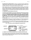
4.8 AC LOCK CONTROL
Many electric locks are intended for operation on 12 or 24 volts AC. The panel, however, only
operates on DC and cannot supply AC from its toggle switch control outputs. Most electric locks
which operate on AC will also operate on DC, so the installer should check this point. If,
however, the locks must operate on AC or on a voltage other than 12 or 24, this can only be
done by using the panel to energize and deenergize relays which operate on the panel voltage.
The relay contacts will then switch the "foreign" lock voltage from a second power supply. This
technique is the same that must be employed if the locks draw more than 1.5 Amps current.
5. OPTION WIRING
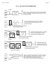
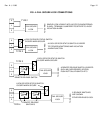
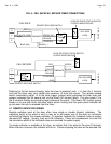
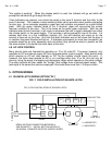
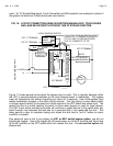
5.1 SILENCE LATCH WIRING (OPTION "SL")
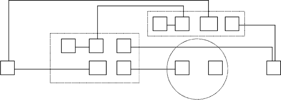
FIG. 7: FIELD INSTALLATION OF SILENCE LATCH
A
-
COM. NEG.
COM
NC
NO
+
-
RELAY
PUSH BUTTON
L+ L-COM
NO
SONALERT
+
-
PANEL TERMINAL
BREAK EXISTING CONNECTION BETWEEN A
AND SONALERT +. INSTALL BUTTON AND RELAY
AS SHOWN. SONALERT NEGATIVE ALREADY WIRED.
FIG. 5: FIELD INSTALLATION OF SILENCE LATCH
L+=INDICATOR +
L-=INDICATOR -