


Rev. A.1, 10/99 Page- 24
keyswitch is in the NO position. Be sure that the keyswitch contacts are of adequate capacity to
switch all the power of the panel.
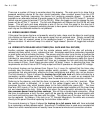
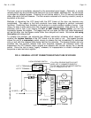
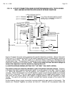
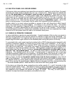
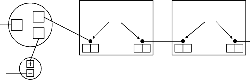
FIG. 13: FIELD INSTALLATION OF BYPASS KEYSWITCH (FAIL SAFE LOCKS)
ALTERNATE ACTION
INDICATOR
SPDT KEYSWITCH
C
NC
NO
TO DC NEG
E4L4
L1 S1
L4E4
L1 S1
OPEN PAD
OPEN PAD
NEXT BOARD ETC
THIS CONNECTION REQUIRES SOLDERING. IDENTIFY
THE 2 OPEN PADS ON EACH BOARD NEXT TO
THE TERMINALS AS SHOWN. PADS ARE
INTERCONNECTED ON ALL BOARDS TO THE
KEYSWITCH N.O. TERMINAL AS SHOWN.
PANEL BOARD PANEL BOARD
+V POWER
Note that when a bypass keyswitch is used together with an emergency release pushbutton
(option “PB”),
the push button is bypassed at the same time the toggles are. This is done by
using a two pole keyswitch. One pole operates as is shown in Figure 13 above. The second
pole bypasses the PB contacts which break the negative DC input to the panel. This is to
maintain the security of the locks regardless of what is done to the panel controls until the
keyswitch is again returned to the “normal” position.
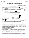
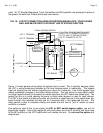
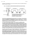
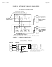
5.5 SWITCH BYPASS WIRING (OPTIONS "KP2" OR "MK2" FAIL SECURE LOCKS)
The option comes pre-wired for whichever type of keyswitch has been chosen. However,
if the panel has been supplied without this option, it may be added in the field. Refer to Figure
14. The keyswitch removes power from all the terminal boards. This bypasses the ability of the
toggles to release the locks. The panel's monitoring capability will also be disabled but the
purpose of the keyswitch is to shut down the panel when the operator is absent so this is not an
issue. Note that the keyswitch indicator (which operates on the same voltage) indicates that the
panel is operating normally. Be sure that any field installed keyswitch has contacts of sufficient
capacity to break all of the panel power. Also, make sure you terminate the lock negative wires
to the panel “-” terminals rather than directly to the power supply or this will not work.
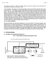
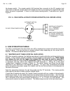
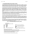
The reason that this option is set up to break the negative circuit instead of the positive is to
preserve the ability to run separate +V inputs to each board zone. This can allow separately
breakered inputs from a Securitron power supply or the installation of upstream switches.
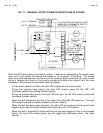
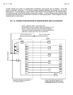
If the installation includes remote release switches, an important change must be made
from the lock wiring in Figure 4. Assuming that you wish the remote release switch to
continue to function when the panel is bypassed, it will not if the job is wired as is shown in type
3 or type 4 hookups in Figure 4. The reason is that keyswitch bypass will remove DC negative
from the panel and hence from the return of the fail secure locks. The solution is to run an extra
DC negative wire from the power supply to the remote switch common. The wire is upstream of