


Rev. A.1, 10/99 Page- 25
the bypass switch. The remote switch’s NO terminal then connects to the DC negative lock
return wire so that the remote switch will release the lock by connecting the negative side even
when the panel is bypassed. If there is a lock status sensing switch, it connects as in type 2,
Figure 4.
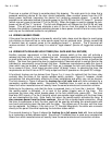
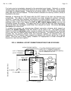
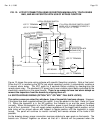
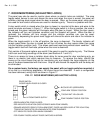
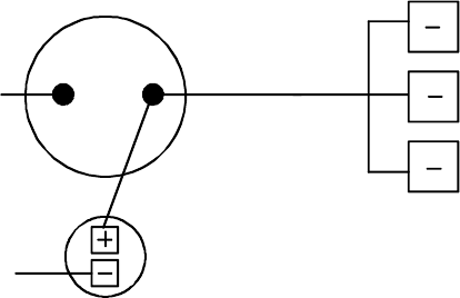
FIG. 14: FIELD INSTALLATION OF BYPASS KEYSWITCH (FAIL SECURE LOCKS)
DC NEG FROM POWER SUPPLY
A
LTERNATE ACTION
INDICATOR
TO DC NEG
SWITCH NC CONNECTS
TO "-" TERMINALS
ON ALL BOARDS
IN PANEL
KEYSWITCH
MAKE SURE EQUIPMENT
AT DOORS TERMINATES
ITS NEGATIVES AT PANEL
"-" TERMINALS
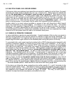
6. USE OF MULTIPLE PANELS
It is often a requirement that more than one LCP is employed to control and monitor the same
group of doors. This can be done in several different ways depending on the control that is
desired. The Sections below discuss the options.
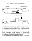
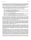
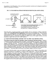
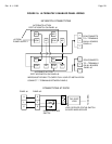
6.1 “MASTER/SLAVE” PANELS (FOR FAIL SAFE LOCKS)
With this connection scheme, the switches are placed in series while the monitoring lights are in
parallel. In the “normal” (secure) condition, the zone toggle on each panel is up.
Either toggle
can release the lock but the toggle that released the lock must be used to resecure it.
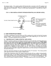
Note that this set-up is well suited for
momentary toggles. Since the switch is spring loaded, it
is automatic that the switch that released the lock resecures it. Wiring for a two panel
“master/slave” installation is shown in Figure 15. The terms “master” and “slave” do not imply
that there is any difference in the boards (or panels). It is just a way of identifying the board
which connects to the power supply (the master) and the one that connects to the equipment at
the doors (the slave).
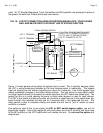
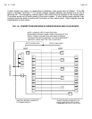
Note the connections between the red flying leads and the “R” terminals. This merely permits
either panel to be able to reset a system violation alarm.
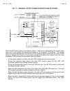
If more than 2 panels are used, the “master” board connects with any number of slave boards.
Referring to Figure 15, the master board and 1st slave board connect as shown. The 2nd slave
board would connect to the 1st slave board with the E and S terminals wired together and with
the L terminals of the first slave board connecting to +1, +2, +3 and +4 of the second. This
continues the series lock power connection. The locks always connect to the last slave board.