


Rev. A.1, 10/99 Page- 13
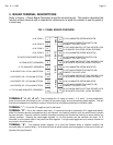
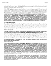
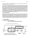
TYPE 1 FAIL SECURE
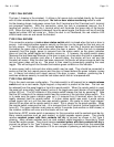
The type 1 drawing is the simplest. It utilizes a fail secure lock controlled directly by the panel
with no other release devices employed. No lock or door status monitoring switch is used.
As the drawing shows, lock power comes from the E terminal and the S terminal and L terminal
are jumpered together. With this connection, when the lock is unpowered (secure), the S
terminal will receive +V from the L terminal which will illuminate the green side of the bicolor
LED. When the lock is powered (released) from the panel toggle, the bicolor will be off and the
toggle bat yellow LED will come on. Since the door is not monitored, the red violation LED
should never come on and sound the Sonalert.
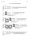
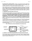
TYPE 2 FAIL SECURE
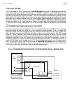
This connection employs a lock or door status switch which is closed when the lock or door is
secure. Lock status provides superior security as the door can be closed but the lock may not
be fully secure. The status switch connects between the L and the S terminal and therefore
illuminates the green side of the bicolor when the door is secure. When the lock is released
(powered) from the toggle, power is removed from the status switch so the green indication
goes out and the yellow toggle bat indicator comes on. If, however, the status switch opens
(because the lock becomes insecure or the door is open) at a time when the lock is unpowered,
this is the violation condition and after a 2 second delay, the bicolor will turn red and the
Sonalert will sound. After the door has been resecured, the bicolor will show orange as both the
red and green sides will be on. The panel is then reset by momentarily pressing the reset
toggle. This will extinguish the Sonalert and restore green condition on the indicator.
In some cases, both a lock and door status switch may be used. They should be connected in
series so that the lock reports secure and the door is closed before the green indicator comes
on. In theory lock status can't report secure if the door is open. However, combining the 2
switches enhances security in case the lock status switch fails or is tampered with.
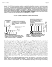
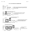
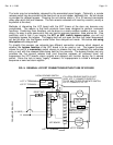
TYPE 3 FAIL SECURE
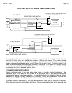
This is the most common configuration. The status switch is still present but a remote release
switch such as a card reader, digital keypad, or keyswitch is present at the door. The lock can
be released from the panel toggle or from this remote switch. When the remote switch is used,
the panel will annunciate "legal release" just as if the toggle was used (bicolor off and toggle bat
yellow LED on). The NO contacts of the remote switch release the lock by powering it. Note
that the NC contacts of the release switch feed the common of the lock/door status switch. This
is to make sure the green indicator goes out (+V removed from S terminal) when the lock is
legally released from the remote switch. If a door status switch was used, it would remain
closed (green light on) until the door was actually opened. We prefer to show "legal release"
(bicolor off) as soon as the remote switch is used. This is clearer for the panel operator. When
the remote switch resecures the lock, +V is removed from the E terminal (yellow toggle bat LED
turns off). The green indicator must come on within 2 seconds (lock secures or door closes) or
the violation condition will occur and the bicolor will turn red.
Note that an SPDT remote switch is necessary for this connection and the contacts must be dry.
Many remote switches such as card readers, or digital keypads require power. They should
receive
constant power with their contacts left dry to connect as shown in the Type 3
drawing. Many remote switches such as card readers, digital keypads or Securitron's Touch
Sense Bar require power. They should receive constant power with their contacts left dry to
connect as shown in the Type 3 drawing. Power is most easily furnished from the associated
“+” terminal for the zone. See section 4.4 for an example of powering a switching device at the
door.