


Rev. A.1, 10/99 Page- 15
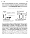
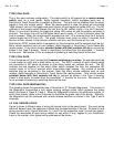
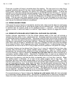
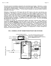
There are a number of things to consider about this drawing. The main point is to show that a
powered switching device at the door should preferably draw constant power from the LCP
board power terminals (assuming the device isn’t receiving separate power). It would be
possible as an alternate method to provide power to the DK-26 from the LCP board “L” terminal
(which now only goes to terminal C1 of the DK-26). When the toggle is used to release the lock,
power will be off the “L” terminal. The fail safe Magnalock will release but the DK-26 will lose
power. This will work and does eliminate a wire in the run from the panel to the door but it
reduces the reliability of powered switching devices to have power turned off and on many times
each day so the alternate method is not prefered.
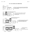
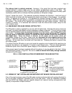
4.5 WIRING UNUSED ZONES
If the panel has zones that are not presently wired to locks, steps must be taken to avoid going
into violation as there will be no zone secure signal from an unwired zone. Simply connect the
E terminal from all unwired zones to the respective board “+” terminal. The E terminal will
receive constant +V which will keep it in a state of "legal release" (bicolor off; toggle bat indicator
on).
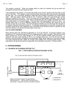
4.6 WIRING WITH RELEASE HOLD TIMER (FAIL SAFE AND FAIL SECURE)
Another common requirement is that the remote release switch at the door will activate a
release hold timer which, in turn, releases the lock. Examples would be a momentary keyswitch
or push button which activates the timer. The person using the door turns the key or pushes the
button. The timer then opens the door for approximately 5 seconds which is enough time for the
individual to conveniently move through the door. Numerous manufacturers make this type of
timer which may be termed a "release hold" timer as it releases the lock and holds the release
for an amount of time. Such timers are also called "off delay" timers. In selecting the timer, the
requirements are that it has an SPDT relay output and that it operates on the panel DC voltage.
A functional hookup can be derived from Figure 3 or 4 once it's realized that the timer relay
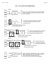
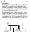
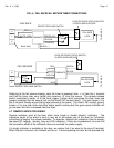
contacts take the place of the remote release switch contacts. Figure 6, however, shows
connections that are particularly effective for timer installations and which may not be obvious.
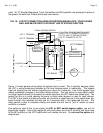
The first drawing in Figure 6 shows the
hookup for a fail safe lock with timer activated by a
momentary remote release switch. Securitron's TimeMate timer is used as an example but
timers from other manufacturers will usually have the same terminals and connection scheme.
Referring to the drawing, note that the timer is powered (red=+ in) from the L terminal. When
the remote switch is activated, +V is input to the yellow (trigger) wire of the timer. This
energizes the timer relay which breaks power to the lock (white=com; green=NC). The timer
blue wire (NO) inputs +V to the E terminal which annunciates legal release until the timer times
out and reenergizes the lock. Note finally that when the remote switch activates the timer,
it
also removes power from the timer common. We call this a double break connection. Were
the timer to experience a fault, the door could still be used by activating the remote switch with
one hand and pushing open the door with the other. This allows use of the door until the timer
can be replaced. As always, if the lock is an "S" Senstat Magnalock, the white wire connects
directly to the panel S terminal replacing the lock/door status switch
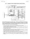
The second drawing in Figure 6 shows the
hookup for a fail secure lock with timer activated
by a momentary remote release switch. Securitron's TimeMate timer is used as an example but
timers from other manufacturers will usually have the same terminals and connection scheme.