


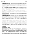
Rev. A.1, 10/99 Page- 6
3. BOARD TERMINAL DESCRIPTIONS
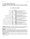
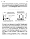
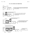
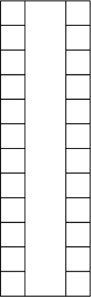
Refer to Figure 1 (Panel Board Overview) to see the terminal layout. This section describes the
function of each terminal and is intended for reference or to allow the installer to use the panel in
a novel way.
FIG. 1: PANEL BOARD OVERVIEW
E1
E2
E3
E4
L1
L3
L4
S1
S2
S3
S4
AY
Y4
Y3
Y2
Y1
A
R
-
+4
+3
+2
+1
DC NEG FROM POWER SUPPLY
+V TO SONALERT (PREWIRED)
CONNECT FAIL SAFE LOCK
+V IN ILLUMINATES GREEN INDICATOR
ZONE 1
ZONE 2
ZONE 3
ZONE 4
CONNECT FAIL SAFE LOCK
+V IN ILLUMINATES GREEN INDICATOR
CONNECT FAIL SAFE LOCK
+V IN ILLUMINATES GREEN INDICATOR
CONNECT FAIL SAFE LOCK
+V IN ILLUMINATES GREEN INDICATOR
+V FROM RESET (PREWIRED)
+V IN, ZONE 3
+V IN, ZONE 1
+V IN, ZONE 2
+V IN, ZONE 4
+V TO PULSING SONALERT (PREWIRED)
+V IN DRIVES YEL. LED #1 (AM OPTION)
+V IN DRIVES YEL. LED #3 (AM OPTION)
+V IN DRIVES YEL. LED #4 (AM OPTION)
+V IN SHUNTS VIOLATION (LEGAL RELEASE)
+V IN SHUNTS VIOLATION (LEGAL RELEASE)
+V IN SHUNTS VIOLATION (LEGAL RELEASE)
+V IN SHUNTS VIOLATION (LEGAL RELEASE)
+V OUT WHEN RESPECTIVE SWITCH ON-
+V OUT WHEN RESPECTIVE SWITCH ON-
+V OUT WHEN RESPECTIVE SWITCH ON-
+V OUT WHEN RESPECTIVE SWITCH ON-
+V IN DRIVES YEL. LED #2 (AM OPTION)
+V OUT WHEN SWITCH OFF/FAIL SECURE LOCK
+V OUT WHEN SWITCH OFF/FAIL SECURE LOCK
+V OUT WHEN SWITCH OFF/FAIL SECURE LOCK
+V OUT WHEN SWITCH OFF/FAIL SECURE LOCK
L2
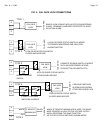
TERMINALS "+1, +2, +3, +4”: They constitute the +V inputs for zones 1, 2, 3, and 4. In most installations,
these four terminals wire directly to the +V output of the power supply and are therefore jumped together. The fact
that they are separate on the board, however, allows the use of upstream switches to individual zones.
TERMINAL "-”: This is the DC negative input for the board.
TERMINAL "R": This is the violation reset input. It is prewired through a momentary N.O. toggle reset switch.
When the Sonalert sounds, accompanied by a red indicator, the violation condition (lock not secure when it should
be) has occurred. Once the violation condition has been corrected, the Sonalert will continue to sound as this is a
latching condition. Pressing the reset toggle supplies +V into this terminal and the condition will reset. All R
terminals on all the board used in the panel are wired together. A single reset toggle serves to reset a violation on
any board in the entire panel.
TERMINAL "A": This prewired output supplies +V to drive the Sonalert when a violation condition has
occurred (after a 2 second delay). All A terminals from all panel boards are wired together so that any of them can
operate the single Sonalert.