


Rev. A.1, 10/99 Page- 1
SECURITRON LCP SERIES ELECTRIC LOCK CONTROL PANEL
INSTALLATION AND OPERATING INSTRUCTIONS
1. DESCRIPTION
1.1 GENERAL
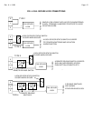
The LCP series is a circuit board based family of control panels suitable for hard wired control
and monitoring of electric locks. The unit can also be used for door monitoring only (no electric
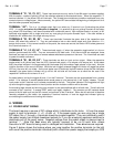
locks). See section 6. The circuit board operates 4 control/monitoring zones so the panel must
be constructed in multiples of 4 zones. The locks must operate on 12 or 24 volts DC and may
be fail safe (secure when powered) or fail secure (secure when unpowered). Lock current draw
is limited to 1.5 Amps (steady) with 3 Amps inrush acceptable.
The LCP series includes several options which are generally supplied with the panel (when
ordered) or in most cases may be added by the installer if the requirement for the option is
discovered after the panel has been delivered.
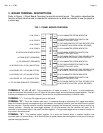
The panel's part number expresses the complete description of the panel as follows:
LCP-XX-YY-(OPTIONS)
"XX" = The number of zones for control and monitoring
"YY" = The panel voltage (12 or 24 VDC)
Options are expressed as letter suffixes as follows:
"W" = Wall mount Nema 1 locked enclosure
"F" = Flush mount pull box cover with back box
"R" = 19" Rack panel face. A slope front desk mount is the standard panel enclosure.
"SL" = Silence Latch
"PB" = Emergency all release (for fail safe locks only)
"AM" = Additional set of monitoring lights
"KP1" or "MK1" = Keyswitch control switch bypass (for fail safe locks only)
"KP2" or "MK2" = Keyswitch control switch bypass (for fail secure locks only)
"MOM" = Momentary control switches (alternate is standard)
“HT” = Substitutes high volume push button switches for toggle switches
As an example, part # LCP-16-12-W-SL-MOM would be a 16 zone, 12 VDC, wall mount panel
with the Silence Latch and momentary switch options installed.
The options are discussed in detail in section 2.
1.2 PANEL POWER
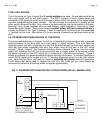
Panel (and lock) power must be from a single power supply of the same voltage required by the
locks (12 or 24 VDC). The panel distributes this power to each lock through its control switches.
Regulated DC is not necessary. A transformer + bridge rectifier is adequate. The rectifier
must however be full wave; a single diode will not work.
A power supply with integral battery backup (available from Securitron) is required if the system
is expected to operate in a power failure.
In selecting the power supply, it naturally should be of sufficient capacity to operate all the locks.
In addition the panel requires power for its internal electronics and indicators. The power