


Rev. A.1, 10/99 Page- 23
NO
NC
C1
C2
C3
+
LS
BP
FE
IN
RS
NC
NC
NO
NO
0V (NEG)
+V
MAGNALOCK
SONA-
LERT
RED
BLACK
+
TOUCH
SENSE
BAR
RED
WHT
MK KEY-
SWITCH
WHITE
RED
LED
RED
GREEN
BLACK
XDT BOARD
LCP "S" TERMINAL
"S" SENSTAT
LCP "Y" TERMINAL
COM
NC
NO
LCP "L" TERMINAL
LCP "E" TERMINAL
LOCAL RELEASE SWITCH
IF A LOCAL RELEASE SWITCH IS NOT
USED, LCP "L" CONNECTS DIRECTLY
TO "C3"; LCP "E" TO "BP"
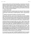
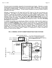
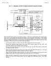
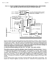
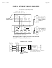
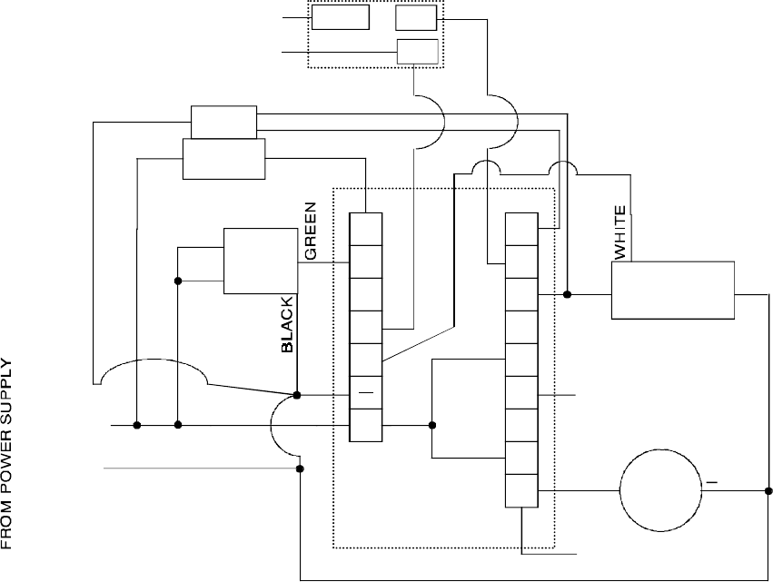
Figure 12 shows the same wiring scheme with specific Securitron products. Note a final point.
Since the LCP is monitoring the XDT's lock status reporting function, it automatically receives a
5 second alarm delay. The XDT waits for 5 seconds before violating by deenergizing the
remote alarm relay. The standard LCP panel has its own violation alarm delay controlled by the
electrolytic capacitors on the panel boards.
There is no reason to have two alarm delays so
remove the capacitors from the boards by clipping them off.
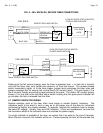
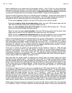
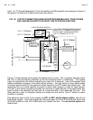
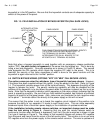
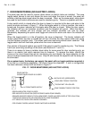
5.4 SWITCH BYPASS WIRING (OPTION "KP1" OR "MK1" FAIL SAFE LOCKS)
The option comes pre-wired for whichever type of keyswitch has been chosen.
However,
if the panel has been supplied without this option, it may be added in the field. Refer to Figure
13. When the keyswitch is in the NC position, the indicator is on and the panel functions
normally. When the keyswitch is in the NO position, power is sent through diodes on the board
to all of the L terminals. They will supply power regardless of the toggle switch position, so fail
safe locks will be pinned secure with respect to toggle position until the keyswitch is again
turned. The panel will continue to monitor normally and remote release of the locks is still
possible.
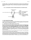
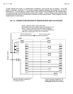
As the drawing shows, proper connection requires soldering to open pads on the boards. The
boards are "chained" together as shown so that all L terminal will be powered when the
FIG. 12: LCP/XDT CONNECTION USING SECURITRON MAGNALOCK, TOUCH SENSE
BAR, AND MK KEYSWITCH WITH USE OF BYPASS FUNCTION