


Rev. A.1, 10/99 Page- 26
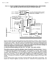
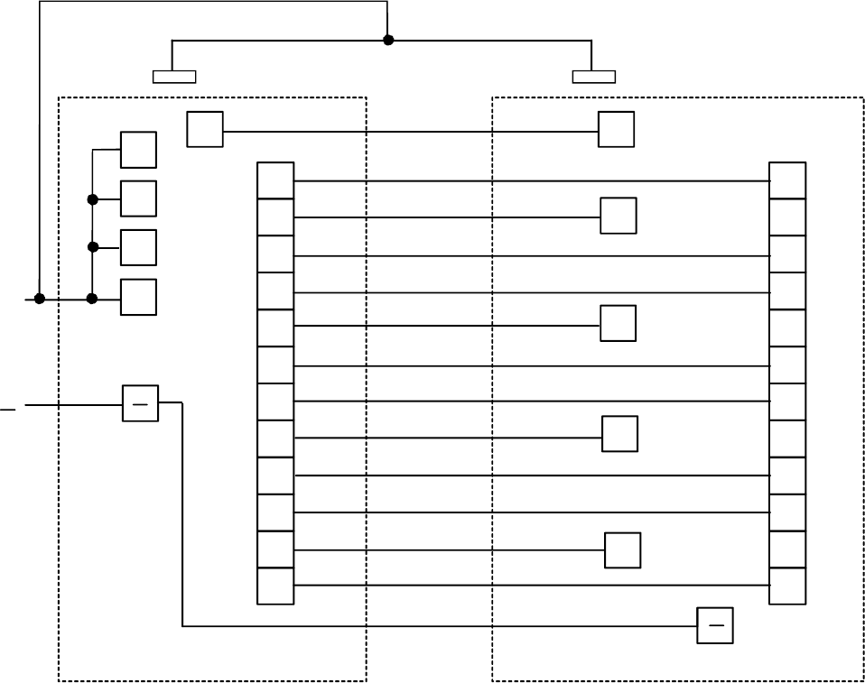
If other options are used in a master/slave installation, they would wire as follows: If the AM
option is present, terminals Y1-Y4 would connect together between the boards just as the S
terminals do. The emergency release option (PB) would only be installed on the master panel.
The button would act to break power to the entire system. If other buttons were desired, their
contacts should be wired in series with the button on the master panel. Switch bypass must be
implemented on each panel.
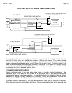
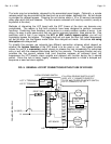
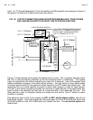
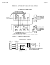
FIG. 15: CONNECTIONS BETWEEN STANDARD BOARD AND SLAVE BOARD
TO POWER SUPPLY
"SLAVE" BOARD CONNECTS TO
LOCAL SWITCHES AND LOCKS
S1
L1
E1
S2
L2
E2
S3
L3
E3
S4
L4
E4
S1
L1
E1
S2
L2
E2
S3
L3
E3
S4
L4
E4
+4
+3
+2
+1
(
TERMINALS S1-S4, L1-L4, E1-E4
)
"MASTER" BOARD CONNECTS
+4
POWER SUPPLY
+
RED FLYING LEAD
NOTE: A SINGLE RED FLYING LEAD WILL
BE PRESENT IN EACH PANEL FROM THE REAR OF THE
RESET TOGGLE (NO MATTER HOW MANY BOARDS).
THIS MUST RECEIVE CONSTANT +V FOR ALARM RESET
AND BOTH LEADS MUST BE TIED TOGETHER.
+3
+2
+1
RR
RED FLYING LEAD