Rev. A.1, 10/99 Page- 20
Most installations do not require use of the bypass function. Even if there is a local authorized
entry or exit device at the door, it will often have its own timed relay output. We believe that the
LCP/XDT combination works more clearly when the
bypass function is not used and therefore
recommend employing the first connection scheme shown in Figure 9 where possible.
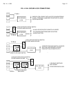
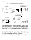
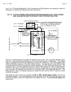
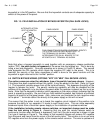
Figure 9 shows the general case of an LCP/delayed exit installation. Delayed exit takes place at
the door as controlled by the initiate and reset switches. The LCP panel serves two functions. It
releases the lock for authorized entry or exit and also monitors the door as follows:
In the normal (
secure) condition, the main LED is green and no alarm sounds.
During the
nuisance delay and release delay period, the main LED remains green but the
"AM" LED illuminates yellow and a pulsing Sonalert sounds.
When the
lock releases at the end of the delay, the yellow AM LED goes out. The main
LED turns red and the steady Sonalert sounds.
When the lock has been
reset (relocked), the main LED turns orange and the panel reset
toggle may be used to halt the Sonalert and restore the main LED to green.
When the lock is
released for authorized use from the panel toggle or from a local release
switch, the main LED turns off and the toggle bat illuminates yellow. No alarm sounds.
Note on the drawing that the local release switch may or may not be present. If no local release
switch is used, LCP terminal "L" connects directly to XDT terminal "C3" and and to the “top” of
the initiate switch (the switch contact that does not connect to “IN”). LCP terminal "E" connects
directly to XDT terminal "FE". If there is more than one local release switch, for authorized exit
and entry for instance, the NC contacts of the two release switches would connect in series.
The NO contacts would each connect to XDT terminal "FE".
There are a number of reasons for the particular wiring method in Figure 9. Note first the
connection to terminal “FE” on the XDT board. Inputting +V to this terminal places the XDT
board in “free egress” mode which means that the lock will release (relay #3 deenergizes),
immediately whenever +V is removed from “IN”. No delayed exit event will begin and the XDT
board’s alarm outputs are suppressed. This is the desired effect when either the panel toggle or
a local release switch has “legally” released the lock.
Note also that the initiate switch is powered not directly from the power supply but rather
through the local release switch. The rationale here is that “IN” should not be powered if either
the local release switch or the panel toggle has released the lock. This permits use of the XDT
board’s “DC” terminal which can keep the lock secure after the delay has expired subject to use
of the initiate device for immediate egress. When this function is employed, it is necessary that
the local release switch or panel toggle can still unlock the door whether or not the initiate
device is used.
A variation to Figure 9 occurs if you are not employing an LCP panel without the “AM” option.
This presents the problem of how to annunciate the release delay period. To accomplish this,
remove the jumper from terminal “LS” to +V. Then connect “LS” to the output of the door/lock
status switch (no longer connect it to the LCP “S” terminal”). Jump “C1” to “C2” and then
connect NO2 to the “S” terminal. With this set-up, the remote alarm relay contact, NO2, will
maintain the green LED on the panel in the secure condition. During a delayed exit event, relay
#2 will deenergize at the end of the nuisance delay period and this will create an immediate
violation alarm at the panel. The same alarm will occur after a five second delay if the door/lock
status sensor reports insecure at any time it should be secure, it its output is connected to “LS”.
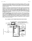
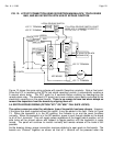
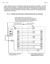
While Figure 9 shows the general approach to wiring the AM version of the LCP into a delayed
exit installation, Figure 10 shows a specific common example where all Securitron products are


