


Rev. A.1, 10/99 Page- 14
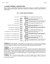
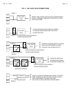
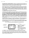
TYPE 4 FAIL SECURE
This is the same as Type 3 except that 2 remote switches are used. An example would be an
entry card reader and an exit push button. The SPDT contacts of each remote switch are
connected in NC series as shown so that the use of either switch cuts power to the status switch
common extinguishing the green indicator. The NO contacts are connected in parallel so that
either switch releases the lock. Any number of remote switches may be connected in this way.
Note that many remote switches such as card readers, digital keypads or Securitron's Touch
Sense Bar require power. They should receive constant power with their contacts left dry to
connect as shown in the Type 4 drawing. Power is most easily furnished from the associated
“+” terminal for the zone. See section 4.4 for an example of powering a switching device at the
door.
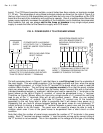
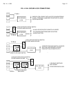
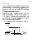
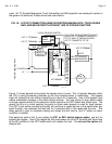
4.4 POWERED SWITCHING DEVICES AT THE DOORS
The wiring methods shown in Figures 3 and 4 do not specifically show operation with a powered
switching device at the door such as a card reader or digital keypad. This is to keep the
drawings simple and also recognizes the fact that powered devices such as card readers will
often get their power separately and only their output relay will be part of the LCP wiring
scheme. When, however, the powered switching device receives its power from the same
supply that operates the LCP, the most convenient way to supply power to the device is from
the power terminals on the LCP board (as is pointed out in the previous sections). Figure 5
shows an example of a powered switching device mounted at the door. It includes Securitron’s
model DK-26 digital entry keypad and an “S” Senstat Magnalock which is a fail safe electric
lock. Note that for clarity, we have not shown a switching exit device such as Securitron’s
Touch Sense Bar being used to release the lock from the inside but you must always be
concerned to adhere to all building codes as regards egress safety.
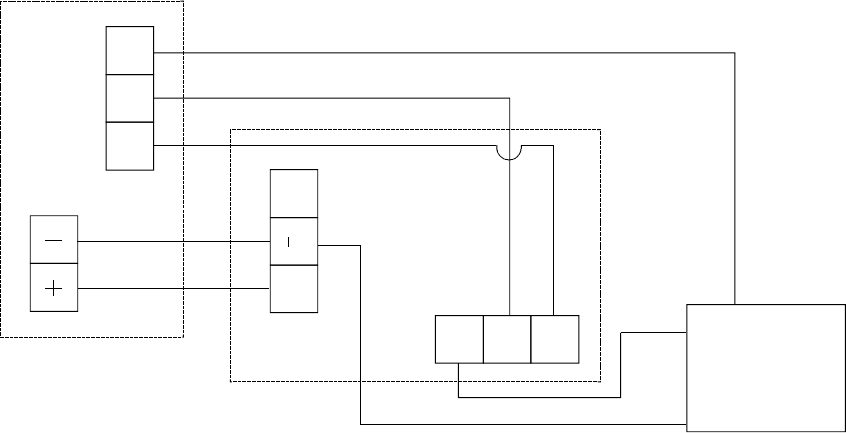
FIG. 5: POWERED SWITCHING DEVICE AT DOOR WIRING (DK-26 + MAGNALOCK)
NC1
C1 NO1
F
DC IN /OUT
+
MAGNALOCK
S
E
L
"S" SENSTAT
DK-26 CPU
RED
BLACK
LCP
BOARD
NOTE: "+" TERMINAL
ON LCP BOARD WILL
BE +1, +2, +3 OR +4
DEPENDING ON ZONE
WHITE