


Rev. A.1, 10/99 Page- 11
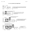
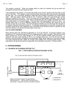
TYPE 3 FAIL SAFE
This is the most common configuration. The status switch is still present but a remote release
switch such as a card reader, digital keypad, keyswitch, switch equipped panic bar, or
Securitron's Touch Sense Bar is present at the door. The lock can be released from the panel
toggle or from this remote switch. When the remote switch is used, the panel will annunciate
"legal release" just as if the toggle was used (bicolor off and toggle bat yellow LED on). The NC
contacts of the remote switch release the lock but the NO contact inputs +V to the E terminal.
When +V is on the E terminal, the toggle bat yellow LED comes on and the violation condition is
shunted. The bicolor turns off as the status switch won't supply +V to the S terminal when the
lock is released. When the remote switch repowers the lock, +V is removed from the E terminal
(yellow toggle bat LED turns off). The green indicator must come on within 2 seconds (lock
secures or door closes) or the violation condition will occur and the bicolor will turn red.
Note that an SPDT remote switch is necessary for this connection and the contacts must be dry.
Many remote switches such as card readers, digital keypads or Securitron's Touch Sense Bar
require power. They should receive
constant power with their contacts left dry to connect as
shown in the Type 3 drawing. Power is most easily furnished from the associated “+” terminal
for the zone. See section 4.4 for an example of powering a switching device at the door.
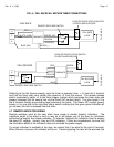
TYPE 4 FAIL SAFE
This is the same as Type 3 except that 2 remote switches are in series. An example would be
a card reader for entry and a push button for exit. The SPDT contacts of each remote switch
are connected in NC series as shown so that either switch can release the lock. The NO
contacts are tied together so that when either switch releases the lock, the respective NO
contact inputs +V to the E terminal which annunciates legal release. Any number of remote
switches may be connected in this manner. Note that many remote switches such as card
readers, digital keypads or Securitron's Touch Sense Bar require power. They should receive
constant power with their contacts left dry to connect as shown in the Type 4 drawing.
Power is most easily furnished from the associated “+” terminal for the zone. See section 4.4
for an example of powering a switching device at the door.
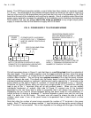
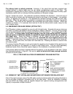
TYPE 5 FAIL SAFE (MAGNALOCK)
This drawing shows the specialized use of Securitron's "S" Senstat Magnalock. This version of
the Magnalock incorporates a lock status sensing voltage output which replaces the status
switch as shown in Types 2, 3 and 4. When the Magnalock is secure, the white wire outputs +V
which then directly inputs to the S terminal to illuminate the green side of the bicolor. Naturally,
the Magnalock can be combined with remote release switches as shown in the Type 3 and 4
drawings.
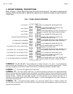
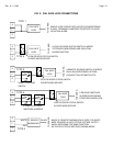
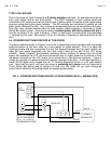
4.3 FAIL SECURE LOCKS
Figure 4 shows 4 different ways of wiring fail secure locks to the panel board. The exact wiring
done will depend upon the equipment utilized and the requirements of the job. All panel to lock
wiring concerns only 3 panel terminals: S, L and E for the respective zone (4 zones per board).
Check the description of each wiring method to see which (if any) applies to your installation.
Later in the manual, other typical wiring schemes will be shown.