


Rev. A.1, 10/99 Page- 2
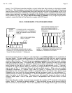
requirements vary with the monitoring scheme and the voltage but figure a worst case of 60 mA
per control zone for panel current draw. Since power supply cost is always a small percentage
of the installation cost, we always recommend to not skimp on power supply capacity. We
advise that the power supply be capable of driving 30% more current than the installation
requires. This eliminates heat induced power supply failure and also allows for some future
expansion of the job.
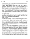
1.3 LOCK CONTROL
Each lock is controlled by a toggle switch on the panel face. Normally, the toggle switch is
alternate action but the "MOM" option supplies spring loaded momentary toggle switches so
that the lock will be released only so long as the switch is held down. It is, of course, possible to
control multiple locks from a single switch (zone) if they are wired in parallel. This is most
commonly done with two locks mounted on a double door. Be sure that if multiple locks are
controlled by a single toggle, the 1.5 Amp current limit per zone is not exceeded. If higher
current control is necessary, the panel should be made to control a relay which in turn will switch
the high current lock or locks. Note that toggle switches are not suitable for high volume use.
50,000 cycles is a typical operating life for a toggle switch. If your expected use for each zone is
on the order of a few dozen operations per day, toggle switches are fine. If the expected use is
in the hundreds of operations per zone per day, you should purchase option HT which replaces
the toggles with illuminated push buttons with a much longer operating life. The lamp within the
“HT” push button, operates just as the toggle bat yellow indicator.
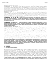
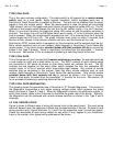
1.4 MONITORING
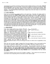
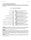
Each zone (toggle switch) has a bicolor LED with
green and red internal elements behind a fresnel
lens. If a second indicator is present for each
toggle, this is the "AM" option which is described in
section 2.3. Returning to the bicolor indicator, the
green element is driven by a separate input terminal
on the board and it is intended to monitor the status
of the lock or door. Green indication means that the
lock is reporting secure if it has lock status sensing
or it can mean that the door is closed from a door
switch. If no lock or door monitoring is desired, the
green indicator can be made to follow the
powered/unpowered status of the lock although this does not utilize the full capabilities of the
panel.
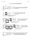
When the lock has been "legally" released from the panel toggle or from a local switch at the
door such as a keyswitch, digital entry device or card reader, the bicolor indicator will be off.
Each toggle switch has a yellow LED in its actuator. This illuminates whenever the lock is
legally released, either from the toggle switch itself being flipped down, or from a local release
switch at the door. The yellow toggle indicator will always correspond to "bicolor indicator off".
If the panel has been supplied with spring loaded momentary switches (option "MOM"),
the toggle switch will not have any indicator due to unavailability from the switch
manufacturer.
The bicolor indicator will turn red in the "violation" condition. This is when the lock should be
secure but is not so reporting from its lock status or door status output.
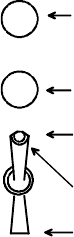
YELLOW LED
(AM OPTION ONLY)
TOGGLE BAT YELLOW LED
LOCK SECURE TOGGLE POSITION
BICOLOR LED (GREEN/RED)
LOCK RELEASE TOGGLE POSITION