


Rev. A.1, 10/99 Page- 27
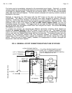
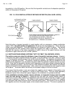
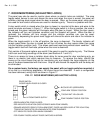
6.2 MULTIPLE PANEL FAIL SECURE WIRING
If fail secure locks are employed and more than one panel is needed to control them, the panel
terminals are simply wired in parallel (S to S; L to L; and E to E). Either panel can release the
lock but
the same panel that released it must be used to resecure it. Both panels monitor
the lock in identical fashion. A single power supply must operate the system and you must
interconnect an “R” terminal from one board in each panel so that all “R’s” are in common. As
always, the red flying leads from the reset toggles must be interconnected with each other and
with a source of +V. Note that this set-up is well suited for
momentary toggles. Since the
switch is spring loaded, it is automatic that the switch that released the lock resecures it.
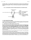
Another option is to mount relays (available in groups of four with Securitron’s RB-4 board)
which are controlled by the panel toggles. The relays in turn control the locks. This allows
altering fail safe operation (magnetic locks for example) to fail secure as when the relay is
energized, it is wired to deenergize the lock through the use of its NC contacts. This technique
can sometimes be useful for a spread out installation where the LCP’s are separated by a large
distance as full lock power does not need to run between each panel.
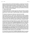
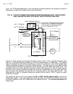
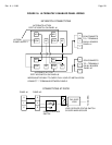
6.3 PANELS ALTERNATELY ENABLED
In some installations, panels are used alternately. A good example of this is when one panel is
manned during working hours and the second is manned at night and during weekends. For
this type of application, it is important that only one panel is enabled at a time as unauthorized
people might be able to gain access to the disabled panel during that portion of the day.
To accomplish this, each panel must be furnished with a DPDT alternate action keyswitch with
contacts of sufficient capacity to handle the full current load of the installation. In the case of
large panels, the keyswitches can operate DPDT relays and then, of course, the keyswitches
only need to be single pole. The factory can supply the keyswitches (Securitron model MKA2
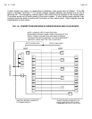
for example) or they may be added in the field. The keyswitch contacts are wired together in 3-
way fashion (see Figure 16) and, therefore,
turning either keyswitch on either panel, at any
time will “flip” the enabled panel. It’s easy to see which panel is enabled as it will show
indicators. The disabled panel will be dark. A single power is required for this to work but
individual breakered outputs are not supported. All positive power input terminals in each LCP
must be jumpered together with the power supply employed as a two terminal device (+ and -).
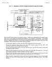
Note on Figure 16 that the
keyswitch contact wires must be heavy enough to carry the full
load of the installation. You must also make sure that each panel is connected to power supply
DC negative either by running power supply negative wires to all the board “-” terminals in each
panel or by running the power supply negative wires to one panel and then interconnecting the
“-” terminals between panels. Make sure this is also done with heavy gauge wires.
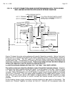
At the doors you follow the same connections from either panel’s S, L and E terminals to the
lock and remote switch (if any). The bottom of Figure 16 gives the example of a type 3 fail safe
lock connection scheme. You must just be sure to
interconnect the S, L and E terminals for
the respective zone between the panels as Figure 16 shows. This way, as each panel is
enabled, its output terminals are properly connected to the lock.