


Rev. A.1, 10/99 Page- 18
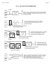
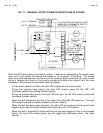
The silence latch is entirely prewired. However, if the panel that has been supplied was
ordered without a silence latch, one can be added comparatively easily in the field. The
components required are an SPDT relay of the panel voltage and an illuminated normally open
momentary switch with an indicator that also operates on the panel voltage.
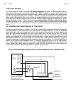
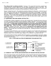
Figure 7 shows the circuit. The prewired connection between the Sonalert + input and one of
the A terminals is broken with the components wired in as shown in the drawing. In a violation
event, +V appears on terminal A. This operates the Sonalert through the COM and NC relay
terminals. When the push button is pressed, it energizes the relay which latches in through its
NO contact. This shuts off the Sonalert and illuminates the push button indicator. When the
violation is cleared, +V is removed from terminal A and the silence latch resets, ready for the
next violation event.
5.2 EMERGENCY RELEASE WIRING (OPTION "PB")
The PB option is factory supplied for use only with fail safe locks. Normally fail secure locks are
not used in a safety type situation where emergency release is desired. The only wiring change
from a standard panel is that the negative terminals of all the boards “-” are already wired to the
push button.
A single black flying lead emerges from the push button and DC negative
external power of sufficient capacity to operate the entire system should be connected to
this black wire. When the button is pressed, all DC power will be broken which will
immediately release all the locks. Make sure you
terminate the lock negative wires at the
panel “-” terminals rather than directly back to the power supply or the push button break will
not work. At the same time, the button will illuminate red. Pressing the button a second time
will restore power.
The reason that the PB option is set up to break the negative circuit instead of the positive is to
preserve the ability to run separate +V inputs to each board zone. This can allow separately
breakered inputs from a Securitron power supply or the installation of upstream switches.
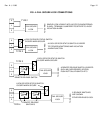
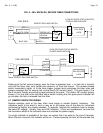
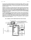
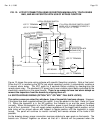
If the present panel has been supplied without this options, it may be added in the field. Follow
the connections shown in Figure 8. Be sure to
select a button with heavy enough contacts
to break all the DC power.
FIG. 8: FIELD INSTALLATION OF EMERGENCY RELEASE BUTTON
COM
NC
NO
ILLUMINATED PUSH BUTTON
ALTERNATE ACTION
L+
L-
DC NEG FROM
POWER SUPPLY
BUTTON NC CONNECTS
TO "-" TERMINALS
ON ALL BOARDS
IN PANEL
L+=INDICATOR +
L-=INDICATOR -
CONSTANT +V
MAKE SURE EQUIPMENT
AT DOORS TERMINATES
ITS NEGATIVES AT PANEL
"-" TERMINALS
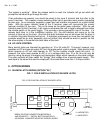
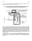
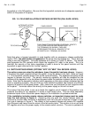
5.3 WIRING OF "AM" OPTION AND SECURITRON'S XDT BOARD FOR DELAYED EXIT
One of the most common uses of the AM option (extra monitoring lights with pulsing Sonalert) is
for an exit delay installation (allowable only for fail safe locks). Such an installation complies
with the NFPA Life Safety code as regards delayed exit (special locking arrangements) and
typically incorporates multiple functions: