


Rev. A.1, 10/99 Page- 22
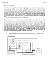
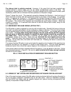
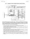
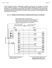
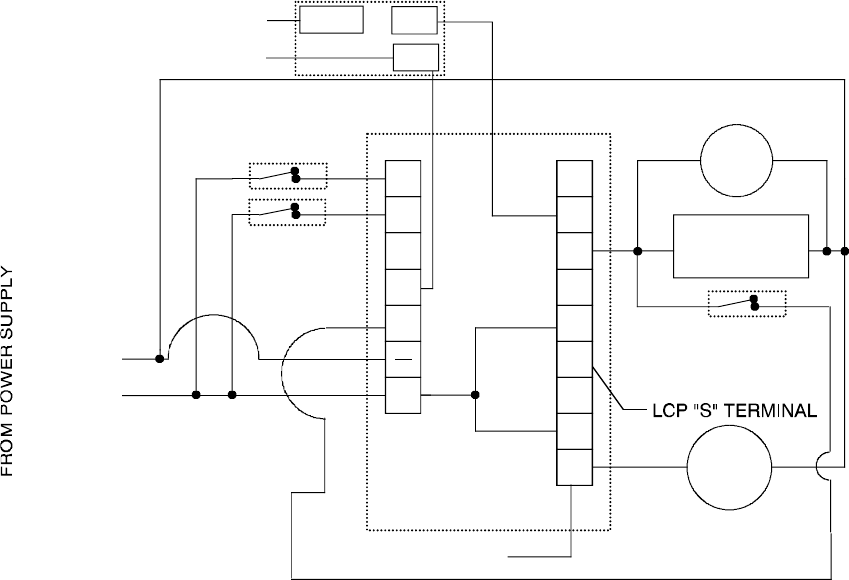
FIG. 11: GENERAL LCP/XDT CONNECTIONS WITH USE OF BYPASS
NO
NC
C1
C2
C3
+
LS
BP
FE
IN
RS
NC
NC
NO
NO
0V (NEG)
+V
RESET (NC)
INITIATE (NC)
FAIL SAFE
LOCK
LOCAL
ALARM
MOV
LCP "Y" TERMINAL
DOOR/LOCK STATUS
SWITCH. CLOSED
WHEN SECURE.
COM
NC
NO
LCP "L" TERMINAL
LCP "E" TERMINAL
LOCAL RELEASE SWITCH
XDT BOARD
IF A LOCAL RELEASE SWITCH IS NOT
USED, LCP "L" CONNECTS DIRECTLY
TO "C3"; LCP "E" TO "BP"
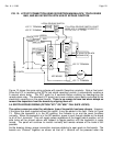
When the XDT does report a lock status violation, it does so by deenergizing the remote alarm
relay, so it is this relay's NO contact that reports in to the panel's "S" terminal. The remote
alarm relay also deenergizes from the end of the nuisance delay period until the lock is reset
during a delayed exit event so the panel's monitoring functions are altered from the ones
discussed in the previous wiring scheme (without bypass):
In the normal (secure) condition, the main LED is green and no alarm sounds.
During the nuisance delay period, the main LED remains green but the "AM" LED
illuminates yellow and a pulsing Sonalert sounds.
During the release delay period, the main LED turns red; the AM LED remains yellow and
the steady Sonalert sounds.
When the lock releases at the end of the delay, the yellow AM LED goes out. The main
LED remains red and the steady Sonalert continues to sound.
When the lock has been reset (relocked), the main LED turns orange and the panel reset
toggle may be used to halt the Sonalert and restore the main LED to green.
When the lock is released for authorized use from the panel toggle or from a local release
switch, the main LED remains green and the toggle bat illuminates yellow. No alarm
sounds.