


Rev. A.1, 10/99 Page- 16
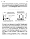
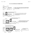
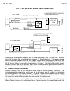
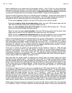
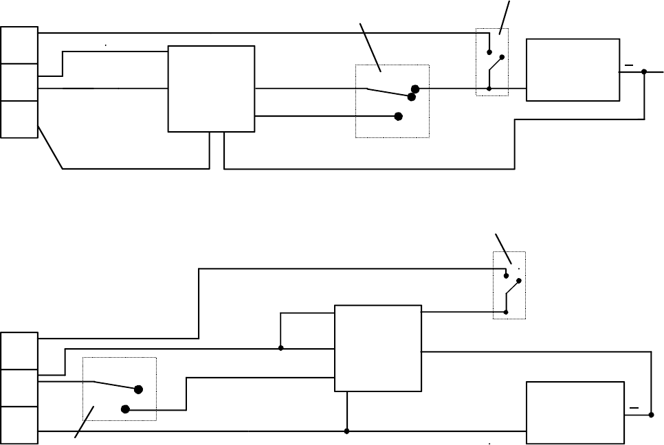
FIG. 6: FAIL SAFE/FAIL SECURE TIMER CONNECTIONS
TO DC NEG
S
E
L
LOCK
+
CLOSED WHEN SECURE
LOCK OR DOOR STATUS SWITCH
FAIL SECURE
REMOTE RELEASE SWITCH
C
O
M
NO
TO DC NEG
C
O
M
NC
NO
S
E
L
FAIL SAFE
LOCK
+
CLOSED WHEN SECURE
LOCK OR DOOR STATUS SWITCH
TIMEMATE
TIMEMATE
RED
BLACK
YELLOW
WHITE
BLUE
GREEN
FAIL SAFE
FAIL SECURE
RED (+)
WHITE (COM)
YELLOW
BLUE (NO)
GREEN (NC)
BLACK (-)
REMOTE RELEASE SWITCH
(TRIGGER)
(TRIGGER)
Referring to the fail secure drawing, note the timer is powered (red= + in) from the L terminal
and that the timer relay com (white) also receives +V from this source. The remote release
switch momentarily inputs +V to the timer trigger (yellow) which energizes the timer relay and
powers (releases) the fail secure lock via the timer's NO contact (blue). This also inputs +V to
the E terminal thereby annunciating legal release at the panel. The timer's NC contact (green)
breaks +V to one side of the lock/door status switch insuring that the green panel indicator will
go out when the lock is released from the timer.
4.7 REMOTE INDICATOR WIRING
Remote switches used at the door often have single or double (bicolor) indicators. The
indicators ought to be wired in such a way as to aid proper use of the door by individuals
authorized to employ the remote switches. To operate, naturally the indicators have to employ
the panel DC voltage. Usually, they are LED indicators. If they are incandescent, be sure that
the cumulative effect of the indicators does not overload the power supply.
If a single indicator is available at the door, we advise that it be wired to the zone S terminal.
When the door is secure, the indicator will be on. Persons passing the door will be assured that