Rev. A.1, 10/99 Page- 8
board. The CCS board provides multiple, current limited two Amp outputs on terminals marked
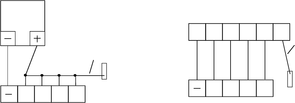
P1, P2 etc. The advantage of using these individual outputs as shown on the right of Figure 2 is
that any short circuit in the downstream wiring will take out only one of the breakers on the CCS
board and the rest of the installation will continue to operate. Use of a multiple output Securitron
power suppy materially increases the reliability of the installation and is therefore recommended.
Note however that you can always add in-line fuses or breakers to any single output power
supply to create the effect of the Securitron supply with CCS board.
FIG. 2: POWER SUPPLY TO LCP BOARD WIRING
+4
+3
+2 +1
POWER
SUPPLY
IF POWER SUPPLY HAS SINGLE
DC OUTPUTS, THE "+" TERMINALS
MUST BE JUMPED TOGETHER AS
SHOWN.
+4 +3 +2 +1
P1 P2 P3 P4R1
SECURITRON POWER SUPPLY
WITH CCS BOARD PERMITS
INDIVIDUAL OPERATION OF "+"
TERMINALS
EACH "P" TERMINAL MAY OPERATE ONE OR
MORE "+" TERMINALS DEPENDING ON THE
NUMBER OF ZONES IN THE PANEL.
P5
RED FLYING LEAD FROM
RESET TOGGLE
RED FLYING LEAD FROM
RESET TOGGLE
NOTE: IF PB OPTION IS SUPPLIED, DC NEG
CONNECTS TO FLYING BLACK LEAD RATHER
THAN TO CIRCUIT BOARD "-" TERMINALS
On both examples shown in Figure 2, note that there is a red flying lead from the underside of
the reset toggle. This wire simply supplies +V to the toggle common and then, when the spring
loaded toggle is pressed, +V is input to the “R” terminal of the board which is used to reset the
violation alarm function. The red flying lead requires constant +V so that the panel violation
alarm can always be reset. The reason why the factory doesn’t connect this wire is that when
individual breakered outputs or ‘upstream” switches are used to operate the “+” terminals on the
board (shown on the right of Figure 2), constant +V cannot be guaranteed to any “+” terminal.
Therefore, as Figure 2 shows, when you have only a single source of +V, connect the red flying
lead to any of the “+” terminals (they will all get constant power). When you can employ
individually breakered +V outputs (right side of Figure 2), connect one of the breakers
separately to the red flying lead in order to guarantee that it will always have power on it.
Supposing that you have to choose between putting two panel zones on one breakered “P”
output terminal or sharing a breakered “P” terminal between a panel zone and the red flying
lead, it is better to do the former. The panel user will expect to always be able to reset a
violation alarm even if one of the panel zones is de-powered from a short circuit or other
condition.
Note that often the number of panel zones exceeds the number of “P” terminals in the power
supply. Each “P” terminal can power multiple “+” input terminals so long as the current rating of
the “P” terminal is not exceeded. This in turn depends on the voltage and the type of lock being


