


39
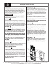
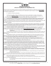
Please Do Not Return This Product To The Store. Call Us Directly! Our Trained Technicians Will Answer Your Questions and/or Ship Any Parts You May Need.
You can reach us Toll Free at 1-888-827-3667 for Consumer Assistance or online at www.wayne-dalton.com
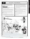
OPERATION
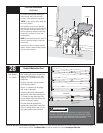
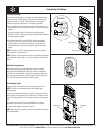
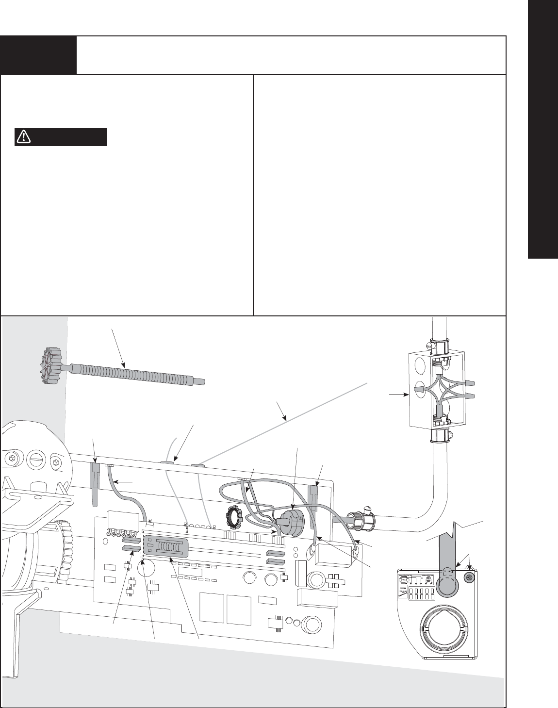
Power Connection — Permanent Wiring Option
If required by local codes, the opener can be permanently
wired. Services of a licensed electrician should be obtained,
to permanently wire the Unit. Disconnect electrical power at
fuse/breaker box.
TO AVOID ELECTRICAL SHOCK, DISCONNECT POWER AT FUSE/
BREAKER BOX BEFORE PROCEEDING.
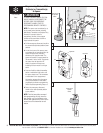
a.
Using a phillips head screwdriver, remove the two screws from the
right hand cover and unplug motor power cable. Remove right
hand cover from the opener to expose electronics and wiring.
b. Remove potentiometer gear. Unsnap the circuit board from the
chassis stand-offs and lower the circuit board as shown.
NOTE: Do not disconnect the two ground wires (A & B) from the
circuit board or the chassis.
c. Using pliers, compress 3 snaps of the strain relief fitting inside
the chassis and push fitting out of the chassis . Cut opener power
cord to a length that will leave 6” inside of the junction box.
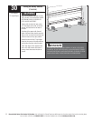
d. Route opener power cable through the conduit. Strip 2 to 3
inches of outer jacket off power cable, insuring individual wire
insulation is not nicked or cut. Strip approximately 3/4” of
insulation off each individual wire. Using wire nuts, splice each
conduit wire with the corresponding wire inside the opener as
follows: opener black (line), opener white (neutral), and opener
yellow and green (ground).
NOTE: Select 1/2” conduit fitting/ J-box that will not interfere with
the opener disconnect cable fittings when disconnect is pulled.
e. Reinstall the circuit board back into the opener chassis and snap
the board back into the chassis stand-offs.
NOTE: Make sure antenna wire is routed through the chassis
grommet and angled 45 degrees to right when board is installed.
f. Confirm pot nut position* shown below.
g. Reinstall the potentiometer gear, right hand cover, and screws.
h. Reconnect Power
❉
WARNING
“A”
“B”
Antenna
Potentiometer Gear
Grommet
Green and Yellow
(Ground)
Chassis
Standoff
Black
(Line)
White
(Neutral)
*Position Pot Nut
1/8” - 3/16” Away
from Left Stop
*Potentiometer
Gear Clip
1/8” – 3/16”
Gap
Strain
Relief Fitting
Junction
Box
View Of Right Hand Side
No Interference
Between Conduit
And Disconnect
Chassis
Standoff