


11
Please Do Not Return This Product To The Store. Call Us Directly! Our Trained Technicians Will Answer Your Questions and/or Ship Any Parts You May Need.
You can reach us Toll Free at 1-888-827-3667 for Consumer Assistance or online at www.wayne-dalton.com
IDRIVE
®
FOR TORQUEMASTER
®
INSTALLATION
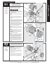
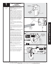
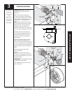
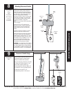
End Bracket Installation
IMPORTANT! WARNING TAGS MUST BE
SECURELY ATTACHED TO BOTH END
BRACKETS.
Slide the right hand end bracket over
the drive gear. Replace #10 phillips head
screw that was removed in Step R3. Secure
end bracket and the flagangle to the jamb
using (2) 5/16” x 1-5/8" lag screws.
NOTE: Older end brackets may not have
a hole needed for the opener’s emergency
disconnect cable. If the right hand end
bracket does not have a hole for the
disconnect cable, drill a 3/32" (3mm) hole
as shown prior to installing the end bracket.
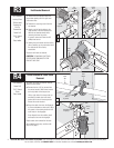
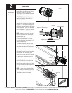
Install the right side counter gear, with
the missing tooth toward the outside and
away from the end bracket. Press the
counter gear onto the end bracket until
snaps engage.
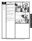
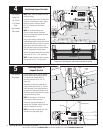
Select the right hand counter cover and
align the hex of the counter cam with
the end of the winding shaft. Also, align the
“0” on the counter cover with the raised rib
on the end bracket. Press the counter cover
against the counter gear until it locks into
place.
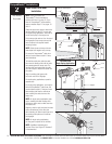
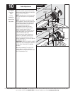
Repeat for left hand side for double
spring applications.
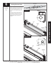
NOTE: No drive gear, counter gear or
counter cover is required on left hand side
for single spring applications. Only an end
bracket is needed.
IMPORTANT! AT THIS TIME DO NOT WIND
COUNTERBALANCE SPRINGS!
After completing this step, continue with
Step 4 on page 12.
Winding
Shaft Inside End
Bracket
Missing
Tooth
Raised Rib
Hex of the
Counter Cam
Counter
Cover
3/32” Hole
5/16 x 1-5/8”
Lag Screws
Counter
Gear
#10 Phillips
Head
Screw
Warning
Tag
1/4”
1/8”
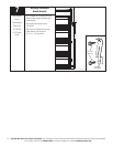
Tools Needed:
Power Drill
3/32” Drill Bit
7/16”
Socket Driver
Phillips Head
Screwdriver
Step Ladder
End Bracket
Flagangle
3