


5
Please Do Not Return This Product To The Store. Call Us Directly! Our Trained Technicians Will Answer Your Questions and/or Ship Any Parts You May Need.
You can reach us Toll Free at 1-888-827-3667 for Consumer Assistance or online at www.wayne-dalton.com
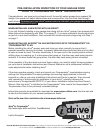
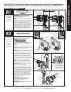
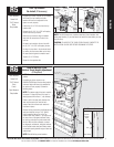
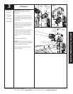
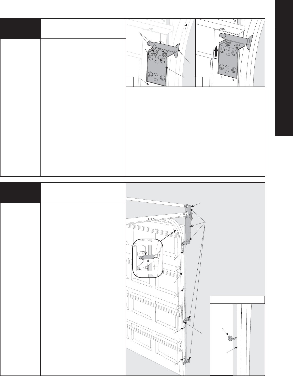
If installing an idrive
®
opener on an installed
9100 door, the top bracket and roller
location will have to be adjusted for the
opener to work properly.
Loosen the (2) 1/4”-20 nuts from the top
bracket slide.
Remove the (4) 1/4”-14 x 5/8" self-tapping
screws from the top bracket.
Raise the top bracket to align the bottom
slots with the second set of holes in the
end cap.
Re-attach top bracket to the end cap with
the (4) 1/4”-14 x 5/8" self-tapping screws.
Re-align the top roller in the horizontal track
by moving the top bracket slide out to force
the door section against the weather seal.
Tighten (2) 1/4”-20 Nuts.
Repeat for the opposite side.
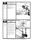
NOTE: The 9100 doors have a painted steel face, foam insulation and
white paper backing. If your door does not match this description you may
skip this step.
CAUTION: TO AVOID THE TOP PANEL FROM FALLING, COMPLETE RE-
INSTALLATION ON ONE SIDE BEFORE BEGINNING THE OTHER.
R5
9100 Top Bracket
Re-Install (If Necessary)
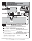
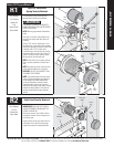
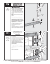
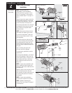
NOTE: The door must be in the fully closed
position.
If installing an idrive
®
opener on an
8000/8100/8200 door, the top roller location
and track height will have to be modified for
the opener to work properly. Perform the
following steps:
NOTE: The bottom edge of the track needs to
be spaced 1” above the floor. If the track is
already spaced off the floor 1”, skip this step.
Fasten a nail in the door jamb, between the
door and the track at the ends of each
section. Bend the nail over each section to
hold them in place.
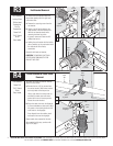
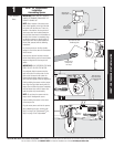
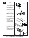
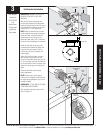
Remove the lag screws from the flagangle and
each jamb bracket. Using a 7/16" socket
driver, loosen the flange nut on the Top
bracket slide. Place a mark 1" up from one of
the tops of one of the jamb brackets. Raise
the track up and align the jamb bracket with
this line. With the track relocated, re-attach
the flagangle, end bracket, and jamb brackets
to the header and/or door jamb. Make certain
to maintain spacing between edge of door and
vertical track.
NOTE: Pilot drill all lag screw locations.
8000/8100/8200 Track
Vertical Track Height Adjustment
(If Required)
a b
Top
Bracket
Slide
1/4” - 20
Carriage Bolts
and Nuts
1/4” - 14 x 5/8”
Self-Tapping
Screws
Top
Roller
Horizontal
Track
Top
Bracket
Remove
Lag Screws
Jamb
Bracket
Flagangle
Nail
Nail
Nail
Nail
Nail Placement
End Cap
Track
Track
Nail bent
over door
section
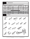
Tools Needed:
Power Drill
7/16" Socket
Driver
Step Ladder
Tools Needed:
Power Drill
7/16" Socket
Drive
Pencil
Tape Measure
Step Ladder
Flange Nut
Top Bracket Slide
(Door Section)
R6
RETRO-FIT