


25
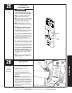
Please Do Not Return This Product To The Store. Call Us Directly! Our Trained Technicians Will Answer Your Questions and/or Ship Any Parts You May Need.
You can reach us Toll Free at 1-888-827-3667 for Consumer Assistance or online at www.wayne-dalton.com
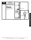
PRE-OPERATION
Receiving
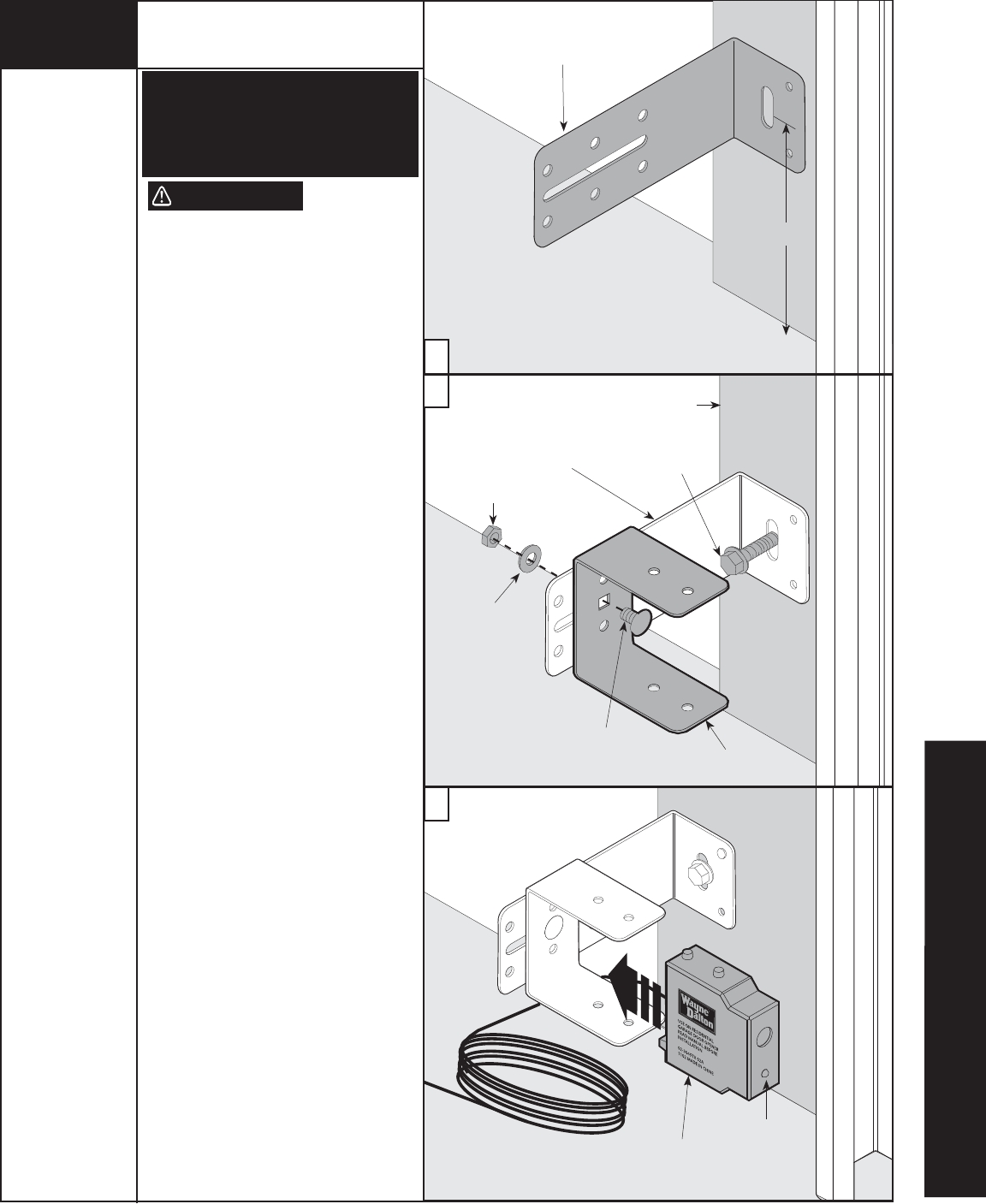
Unit
LED
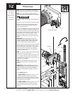
Washer
Nut
1/4”-20 x 1/2”
Carriage Bolt
5/16 x 1-1/2”
Lag Screw
Door Jam
U-Bracket
Wall Mounting
Bracket
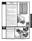
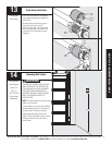
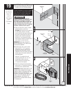
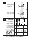
NOTE (Per UL): Safety sensors are required
if opener is installed on a non-pinch resistant
door. If your door is a Wayne-Dalton 9000
series, 5120 or 5140 pinch resistant door,
skip this step and proceed with Step 22.
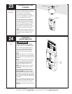
WARNING
PHOTOELECTRIC EYES ARE NOT RE-
QUIRED ON WAYNE-DALTON SERIES 9000
AND MODEL 5120 AND 5140 DOORS.
ALL OTHER DOORS, WHICH DO NOT HAVE
PINCH-RESISTANT SECTION JOINTS, RE-
QUIRE PHOTOELECTRIC EYES TO PREVENT
POSSIBLE SEVERE OR FATAL INJURY.
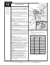
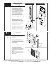
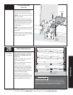
a. Select and mark with a pencil, a suitable
mounting location no more than
5 inches above the floor to the center line
of wall mounting bracket. The safety
sensors should be mounted as close to the
door track or inside edge of the door as
possible to offer maximum entrapment
protection. It is very important that both
wall mounting brackets be mounted at the
same height for proper alignment.
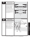
IMPORTANT! BOTH WALL BRACKETS
MUST BE MOUNTED AT THE SAME HEIGHT
FOR PROPER ALIGNMENT.
b. Drill pilot holes, using a 3/16” drill bit.
Using two 5/16” x 1-1/2” lag screws,
permanently mount the wall mounting
brackets to both door jambs. In some
installations it may be necessary to attach a
wooden spacer to the wall to achieve the
required alignment.
Attach the “U” brackets to the wall
mounting brackets with 1/4”-20 x 1/2”
carriage bolts, washers and nuts.
Insert the bolts from the inside of the
“U” bracket and hand-tighten.
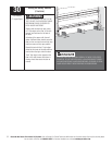
c. Attach the sending and receiving safety
sensors to the “U” brackets by inserting all
three tabs into the respective holes.
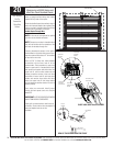
IMPORTANT! IDENTIFY WHICH SIDE OF THE
GARAGE DOOR IS EXPOSED TO THE MOST
SUNLIGHT. MOUNT THE SENDING UNIT (UNIT
WITHOUT LED) ON THE SIDE WHICH IS
EXPOSED TO THE MOST SUN. SUNLIGHT MAY
AFFECT THE SAFETY SENSORS, AND THIS
POSITIONING WILL HELP REDUCE THE
ADVERSE EFFECT SUNLIGHT MAY HAVE ON
THE SENSOR UNIT.
a
b
c
Wall Mounting
Bracket
5”
19
Tools Needed:
Tape Measure
Power Drill
3/16" Bit
7/16” Socket
Driver
7/16” Wrench
Pencil
Safety Sensors Installation
8000 Series Doors (Required) (Not Required
On 9000, 5120 & 5140 Series Doors)