


26
Please Do Not Return This Product To The Store. Call Us Directly! Our Trained Technicians Will Answer Your Questions and/or Ship Any Parts You May Need.
You can reach us Toll Free at 1-888-827-3667 for Consumer Assistance or online at www.wayne-dalton.com
P
E
1
2
S1 S2 S3 S
4
LearnD
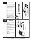
Controls
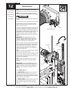
Wire Routing
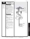
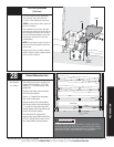
20
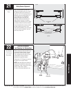
Uncoil wires from photoelectric sensors and route
wires up garage wall and along door header
towards the right side of the opener
.
Route wires behind torque tube and tack wires in
place with insulated staples (not supplied).Take
care to run wires in a location where they will not
interfere with the operation of the door.
Do Not Staple Through Wire.
NOTE: If wires must be lengthened or spliced
use wire nuts or suitable connectors.
NOTE: Take care to run wires in a location where
they will not interfere with the operation of the
door and do not staple through wire.
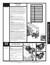
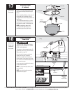
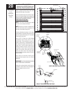
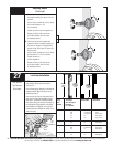
Connect photoelectric sensors to the opener
terminal block on right side of the opener. Sepa-
rate wire ends and strip about 1/2” of insulation
off each of the wire ends.
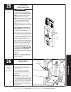
Insert a 3/32” (2.5mm) max. width fl atblade
screwdriver into the lower hole #1 of the
terminal block. Twist screwdriver to open wire
clamp in upper hole #1 of terminal block. Insert
both sender and receiver solid white wires into
upper hole #1 until the wires bottom out and
release screwdriver tension. Insert and twist
screwdriver in lower hole #2 and insert both
sender and receiver wires (white with black
stripe) into upper hole #2 until wires bottom
out and release screwdriver tension. Be sure to
observe polarity.
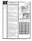
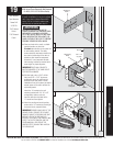
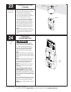
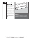
Once wires are connected, install jumper
through the front opener cover on to the pins
labeled PE.
IMPORTANT! KEEP SENDER/RECEIVER WIRES
AWAY FROM MOVING COMPONENTS.
Lightly pull on external wires to test for secure
connection. Check that the wires are stapled in
place and staples have not cut wire
insulation.
Insert screw
driver into
lower hole #1
Insert wires
into upper
hole #2
Insert wires
into upper
hole #1
Insert screw
driver into lower
hole #2
White wires with
black stripe
Solid white wires
RIGHT HAND SIDE VIEW OF OPENER
Jumper
installed
Jumper
Pins labeled
“PE”
VIEW OF THE OPENER FROM THE FRONT
Tools Needed:
Flat Tip
Screwdriver
Pliers/Wire
Cutters
Sensor Wire Installation
(Required on all 8000 Series and
other Non Pinch Resistant Doors)