


12
Please Do Not Return This Product To The Store. Call Us Directly! Our Trained Technicians Will Answer Your Questions and/or Ship Any Parts You May Need.
You can reach us Toll Free at 1-888-827-3667 for Consumer Assistance or online at www.wayne-dalton.com
S1
S2
S3 S4
Learn Delete
Controls
ww
w
.Wayne-Dalt
o
n.c
o
m/
access
Fin
d
ou
t
mor
e
:
what’s
OPENING
you
r
world?
Wi
th Z-
W
ave
®
t
e
ch
no
lo
gy
y
ou
can
contr
ol y
ou
r
lig
h
t
s,
th
e
rmos
t
at
and
s
tar
t
your
m
o
r
n
ing
co
f
fee
,
all with
th
e sing
le
t
o
u
ch
of a
but
ton
.
P/
N
33598
2
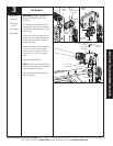
Z-Wave
®
enabled
S1
S2
S3 S4
Learn Delete
Controls
w
ww
.Wayne-Dalt
o
n.c
o
m/
access
Fin
d
ou
t
mor
e
:
what’s
OPENING
yo
ur world?
Wi
th Z-Wave
®
t
ech
no
lo
gy
y
ou
can
contr
ol
y
ou
r
light
s,
th
e
rmos
t
at
and
s
t
ar
t
your
mo
r
n
ing
co
f
fee
,
al
l
with
t
h
e sing
le
t
o
u
c
h
of a
but ton
.
P/
N
33598
2
Z-Wave
®
enabled
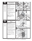
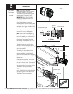
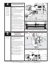
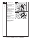
Positioning Support Bracket
NOTE: idrive
®
must be installed on a solid
mounting surface.
Locate the mounting surface. The mounting
surface is a vertical board running directly
above the center of the door. Remove
(2) 1/4”-20 flange nuts from bottom
of opener.
NOTE: Do not discard flange nuts.
Place the support bracket underneath
opener, to the right side of motor, centered
on mounting surface.
Using a tape measure, maintain equal
measurements between torque tube and top
of door at both ends and in center to ensure
torque tube is level. Once torque tube is
level, with idrive resting on support bracket,
drill 1/8” pilot holes for the lag screws.
Now secure support bracket to the mounting
surface with (2) 1/4” x 1-1/2" lag screws.
NOTE: If wood mounting surface is covered
with dry wall, use 1/4” x 2” lag screws.
1/4 x 1-1/2”
Lag Screws
Support
Bracket
1/4” - 20
Flange Nuts
Mounting
Studs
Mounting
Surface
(Header)
Top Of Door
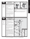
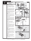
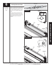
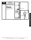
Attaching Opener To
Support Bracket
Lift and slide the opener over the support
bracket, aligning the mounting studs with
the bracket slots. Loosely fasten to
mounting studs with the (2) 1/4”-20
flange nuts.
Alternately, the disconnect cable can be
pulled to allow motor to pivot up. This will
enable assembly of the support bracket to
the opener first, followed by leveling of the
torque tube and then attachment of support
bracket to mounting surface.
NOTE: Do not tighten 1/4”-20 flange
nuts to opener studs at this time.
Remove the orange label holding the
antenna wire. Straighten antenna wire and
angle it 45 degrees to the right.
NOTE: Do not coil the antenna wire. This
will reduce the radio signal range.
Antenna Wire
(2) 1/4”-20
Flange Nuts
Support
Bracket
Mounting
Studs
45° Angle
Tools Needed:
Step Ladder
Bracket
Slots
Torque Tube
Torque Tube
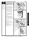
S1S2S3S4
Learn Delete
Controls
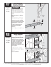
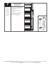
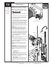
USING A TAPE MEASURE, MAINTAIN AN EQUAL MEASUREMENT “X” (TOP OF DOOR
TO BOTTOM OF TORQUEMASTER
®
TUBE) AT BOTH ENDS AND THE CENTER.
TOP SECTION
“X” “X” “X”
Tools Needed:
Power Drill
1/8” Drill Bit
7/16” Socket
Driver
Tape Measure
Step Ladder
4
5