


MARK 3 USER INSTRUCTIONS ENGLISH 71569102 08-06
Page 53 of 68 flowserve.com
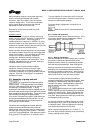
Never compress the snap ring
unless it is positioned around the shaft and between
the bearings. In this configuration, it is contained
therefore if it should slip off the compression tool it
is unlikely to cause serious injury.
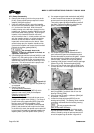
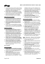
d) The shaft, bearings, and bearing carrier
assembly (figure 6-14) can now be installed into
the bearing housing [3200]. The bearing carrier
[3240] should be lubricated with oil on the O-rings
and threads before installing the assembly into
the bearing housing. Thread the bearing carrier
into the bearing housing by turning it clockwise to
engage the threads. Thread the carrier onto the
housing until the carrier flange is approximately
3 mm (
1
/
8
in.) from the housing. Install the set
screws [6570.3] loosely.
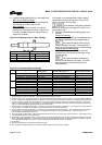
e) Reinstall any tags, plugs, site gages and oiler.
Mark 3 and Mark 3A design
Install the following items onto the bearing housing;
oil level tag (figure 6-18) and combination Trico
oiler/site gage [3855], vent/breather [6521] and
drain plug [6569.1].
ANSI 3A design
Install the following items onto the bearing housing;
oil level tag (figure 6-18) and site gage [3855], plug
[6521] and magnetic drain plug [6569.4].
f) On Group 2 and 3 pumps, assemble the bearing
housing adapter [1340] to the bearing housing
[3200]. Be sure to install a new O-ring [4610.1].
Mark 3 In-Line design
The adapter O-ring [4610.1] should not be installed
if there is a drain tap in the adapter [1340]. This tap
is present on pumps with regreasable bearings and
most oil mist applications.
Mark 3A and ANSI 3A design
Thread the capscrews [6570.5] through the adapter
and into the tapped holes in the bearing housing.
Mark 3 design
Use the capscrews [6570.5] and hexnuts [6580.8].
Orient the bearing housing adapter with the two
holes for capscrews [6570.5] on a horizontal line.
g) If the pump has lip seals, install the deflector [2540].
h) If the pump is equipped with a hook type sleeve
[2400], slip it into place over the impeller end of
the shaft [2100].
6.9.2 Wet end assembly
6.9.2.1 Cartridge mechanical seals
Review the seal assembly instructions and drawings
provided by the seal manufacturer.
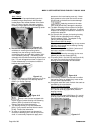
a) Install a nose cone on the end of the shaft and
then slide the cartridge seal [4200] onto the shaft
until it lightly touches the bearing housing [3200]
or adapter [1340]. (See figure 6-10.)
b) Install the rear cover plate [1220] to the bearing
housing (Group 1) or the bearing housing adapter
(Group 2 and 3) by using the capscrews [6570.2].
Now install the cartridge seal gland to the rear cover
plate [1220] using studs [6572.2] and nuts [6580.2].
c) Install the impeller [2200] as instructed in section
6.6. Care should be taken in the handling of high
chrome iron impellers.
d) Tighten set screws on the seal to lock the rotating
unit to the shaft. Finally, remove centering clips
from the seal.
6.9.2.2 Component type mechanical seal
Review the seal assembly instructions and drawings
(seal set dimension) provided by the seal manufacturer.
In order to properly set a component seal it is necessary
to first locate the shaft in its final axial position. This is
accomplished in the following manner.
a) Install the rear cover plate [1220] to the bearing
housing (Group 1) or the bearing housing adapter
(Group 2 and 3) by using the capscrews [6570.2].
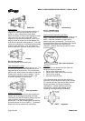
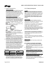
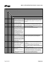
b) Install and set the impeller [2200] clearance as
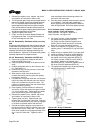
outlined in section 6.6. Put blueing on the shaft/
sleeve in the area near the face of the seal
chamber (rear cover 1220]. Scribe a mark on the
shaft at the face of the seal chamber (figure 6-27).
Figure 6-27
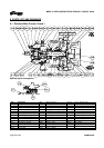
c) Remove the impeller and seal chamber (rear cover)
following the instructions given in section 6.7 and
install a nose cone onto the end of the shaft.
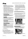
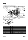
Single internal seal installation
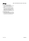
d) Place the gland [4120] and stationary seat onto
the shaft until it lightly touches the bearing
housing (Group 1) or adapter (Group 2 and 3).
e) Install a gland gasket [4590.3] into the gland.
(See figure 6-28.)
Figure 6-28