


MARK 3 USER INSTRUCTIONS ENGLISH 71569102 08-06
Page 12 of 68 flowserve.com
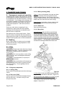
3.3 Design of major parts
3.3.1 Pump casing
Removal of the casing is not required when performing
maintenance of the rotating element. The pump is
designed with a gasket perpendicular to the shaft
allowing the rotating element to be easily removed
(back pull out).
3.3.2 Impeller
Depending on the product, the impeller is either reverse
vane or open.
3.3.3 Shaft/sleeve
Solid and sleeved shafts are available, supported on
bearings, threaded impeller end and keyed drive end.
3.3.4 Pump bearings and lubrication
Ball bearings are fitted as standard and may be either
oil or grease lubricated.
3.3.5 Bearing housing
Large oil bath reservoir.
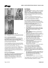
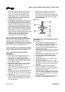
3.3.6 Seal chamber (cover plate)
The seal chamber has a spigot (rabbet) fit between
the pump casing and bearing housing (adapter) for
optimum concentricity. The design enables a number
of sealing options to be fitted.
3.3.7 Shaft seal
The mechanical seal(s), attached to the pump shaft,
seals the pumped liquid from the environment. Gland
packing may be fitted as an option.
3.3.8 Driver
The driver is normally an electric motor. Different drive
configurations may be fitted such as internal combustion
engines, turbines, hydraulic motors etc driving via
couplings, belts, gearboxes, drive shafts etc.
3.3.9 Accessories
Accessories may be fitted when specified by the
customer.
3.4 Performance and operation limits
This product has been selected to meet the
specification of your purchase order. See section 1.5.
The following data is included as additional information
to help with your installation. It is typical, and factors
such as liquid being pumped, temperature, material of
construction, and seal type may influence this data. If
required, a definitive statement for your application can
be obtained from Flowserve.
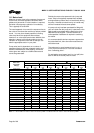
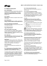
3.4.1 Alloy cross reference chart
Figure 3-2 is the Alloy cross-reference chart for all
Mark 3 pumps.
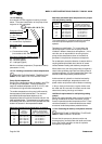
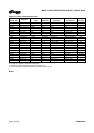
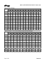
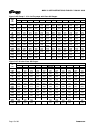
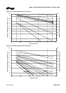
3.4.2 Pressure-temperature ratings
The pressure-temperature (P-T) ratings for Mark 3
pumps are shown in figures 3-3 and 3-4. Determine
the appropriate casing “Material Group No.” in Figure
3-2. Interpolation may be used to find the pressure
rating for a specific temperature.
Example:
The pressure temperature rating for an ANSI
standard GP2-10 in. pump with Class 300 flanges
and CF8M construction at an operating temperature
of 149 Û&LVIRXQGDVIROORZV
a) The correct pressure-temperature chart is Figure
3-4C.
b) From Figure 3-2, the correct material group for
CF8M is 2.2.
c) From Figure 3-4C, the pressure-temperature
rating is 21.5 bar.
The maximum discharge pressure must be less
than or equal to the P-T rating. Discharge pressure
may be approximated by adding the suction pressure
and the differential head developed by the pump.
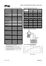
3.4.3 Suction pressure limits
The suction pressure limits for Mark 3 pumps with
reverse vane impellers is limited by the values given in
figure 3-5 and by the P-T ratings.
Suction pressure for pump sizes 10x8-14, 8x6-16A,
10x8-16 and 10x8-16H (up to a maximum liquid
specific gravity of 2.0) is limited only by the P-T
ratings. Suction pressure for pumps with open
impellers is also limited only by the P-T ratings.
The suction pressure limits for Sealmatic pumps are
determined by the repeller head capability found in
Bulletin P-18-102e.
3.4.4 Minimum continuous flow
The minimum continuous flow (MCF) is based on a
percentage of the best efficiency point (BEP). Figure
3-7 identifies the MCF for all Mark 3 pump models
with the exception of the Lo-Flo pump line; there is no
MCF associated with this product line.
3.4.5 Minimum suction pipe submergence
The minimum submergence is shown in figure 3-8
and 3-9 for Unitized self-priming pumps.