


MARK 3 USER INSTRUCTIONS ENGLISH 71569102 08-06
Page 21 of 68 flowserve.com
f) After leveling the baseplate, tighten the anchor
bolts. If shims were used, make sure that the
baseplate was shimmed near each anchor bolt
before tightening. Failure to do this may result in
a twist of the baseplate, which could make it
impossible to obtain final alignment.
g) Check the level of the baseplate to make sure
that tightening the anchor bolts did not disturb
the level of the baseplate. If the anchor bolts did
change the level, adjust the jackscrews or shims
as needed to level the baseplate.
h) Continue adjusting the jackscrews or shims and
tightening the anchor bolts until the baseplate is
level.
i) Check initial alignment. If the pump and motor
were removed from the baseplate proceed with
step j) first, then the pump and motor should be
reinstalled onto the baseplate using Flowserve’s
factory preliminary alignment procedure as
described in section 4.5, and then continue with
the following. As described above, pumps are
given a preliminary alignment at the factory. This
preliminary alignment is done in a way that
ensures that, if the installer duplicates the factory
conditions, there will be sufficient clearance
between the motor hold down bolts and motor foot
holes to move the motor into final alignment. If the
pump and motor were properly reinstalled to the
baseplate or if they were not removed from the
baseplate and there has been no transit damage,
and also if the above steps where done properly,
the pump and driver should be within 0.38 mm
(0.015 in.) FIM (Full Indicator Movement) parallel,
and 0.0025 mm/mm (0.0025 in./in.) FIM angular. If
this is not the case, first check to see if the driver
mounting fasteners are centered in the driver feet
holes. If not, re-center the fasteners and perform a
preliminary alignment to the above tolerances by
shimming under the motor for vertical alignment,
and by moving the pump for horizontal alignment.
j) Grout the baseplate. A non-shrinking grout
should be used. Make sure that the grout fills
the area under the baseplate. After the grout
has cured, check for voids and repair them.
Jackscrews, shims and wedges should be
removed from under the baseplate at this time.
If they were to be left in place, they could rust,
swell, and cause distortion in the baseplate.
k) Run piping to the suction and discharge of the
pump. There should be no piping loads
transmitted to the pump after connection is
made. Recheck the alignment to verify that
there are no significant loads.
4.5 Initial alignment
4.5.1 Horizontal initial alignment procedure
The purpose of factory alignment is to ensure that the
user will have full utilization of the clearance in the
motor holes for final job-site alignment. To achieve
this, the factory alignment procedure specifies that
the pump be aligned in the horizontal plane to the
motor, with the motor foot bolts centered in the motor
holes. This procedure ensures that there is sufficient
clearance in the motor holes for the customer to field
align the motor to the pump, to zero tolerance. This
philosophy requires that the customer be able to
place the base in the same condition as the factory.
Thus the factory alignment will be done with the base
sitting in an unrestrained condition on a flat and level
surface. This standard also emphasizes the need to
ensure the shaft spacing is adequate to accept the
specified coupling spacer.
The factory alignment procedure is summarized
below:
a) The baseplate is placed on a flat and level
workbench in a free and unstressed position.
b) The baseplate is leveled as necessary. Leveling
is accomplished by placing shims under the rails
of the base at the appropriate anchor bolt hole
locations. Levelness is checked in both the
longitudinal and lateral directions.
c) The motor and appropriate motor mounting
hardware is placed on the baseplate and the motor
is checked for any planar soft-foot condition. If any
is present it is eliminated by shimming.
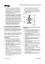
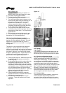
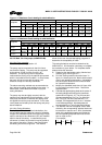
d) The motor feet holes are centered on the motor
mounting fasteners. This is done by using a
centering nut as shown in figure 4-6.
Figure 4-6
e) The motor is fastened in place by tightening the
nuts on two diagonal motor mounting studs.
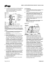
f) The pump is put onto the baseplate and leveled.
The foot piece under the bearing housing is
adjustable. It is used to level the pump, if necessary.
Mark 3A and ANSI 3A design
If an adjustment is necessary, add or remove
shims [3126.1] between the foot piece and the
bearing housing.